This thread has been locked.

If you have a related question, please click the "Ask a related question" button in the top right corner. The newly created question will be automatically linked to this question.

TLV3404: TLV3404: Piezo element // 2 stage op-amp design

Part Number: TLV3404
Other Parts Discussed in Thread: OPA348, TLV3012

Hi,

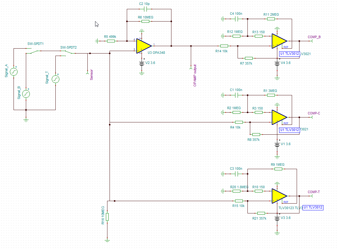
With the support from this forum I have been working on a design of a 2 stage op-amp design. This design uses an OPA348 and a TLV3012. Purpose of the design is to detect the signal of the piezo element at MCU thru an INT. The piezo signal is relatively small (20mV).

The idea was to amplify the signal (1st stage) and in a 2nd stage have a comparator who is connected to an MCU.

  1. Opamp: gain of e.g. 21.
  2. Comparator: At a defined threshold level the output of the comparator is switched to “high” and detected by the MCU.


Simulation

In the TINA simulation I created an input signal for the op-amp of 30 mV and the op-amp output rises to approx. 630mV (gain of 21).

So the simulation works just fine (see schema). We have 3 signal levels which we would like to detect / only 1 sensor signal is that smaal that we have to amplify it. The others go directly to the comperator.


Real-live

In real live (prototype PCB) however I do not see the opamp output rising as I expected.

 The opamp output does not follow the input * gain

  • When driving the op-amp input to approx. 60-70 mV the opamp output suddenly rises to max output.


I am puzzled where the above behavior comes from or if there is anything which I am overlooking. Any help or suggestions are welcome.


Thanks a lot.


  • Hi Jeroen,

    From your comments above I understood that your comparator circuit is working fine but not the op amp circuit (OPA348) that goes into "COMP_B" is this correct?

    Is the output of OPA348 always at VCC (3.6V) or does it show normal gain (G =21) behavior for certain input voltages?

    Can you please probe the non-inverting input and output of OPA348 and share the scope captures on here? 

    Best Regards,

    Bala Ravi

  • Hello Jeroen,

    I see a minor and major issue in the design.

    The minor issue is that the negative voltage half of the input will not be amplified. That is OK as I expect you don't need that half. If the voltage on the piezo gets too large (more than about -400mV) then diode current can flow out of the OPA348 input pin. A series resistor can be use to keep this current flow low. The OPA348 is resistant to phase reversal; that that is helpful. However the overload recovery time can be in play coming out of the VOL state (signal delay). 

    The major issue is R8 and R21. These hysteresis resistors will inject current back to the piezo which is not a good thing (for the other comparator and op amp). In the simulation the source signals have a zero impedance; so they are not affected by the hysteresis current flow.

    Because it is a new design check that everything (including grounds)  is connected properly.

  • Hi Bala,

    Thanks for your feedback.

    Now focussing to verify why the opamp circuit is not working (comperator to be checked in details)

    When the output of the OPA348 rises it goes all the way up to the max (VCC)

    I will send you some scope captures in the coming days.

    Rgds, Jeroen

  • Hi Ronald,

    That's good feedback.

    I am aware of the "minor issue" you mentioned. The negative voltage which gets lost "after" the opamp is not an issue in this design :-) A series resistor might be good idea when input voltages gets higher (> 400mV).


    The major issues is indeed something which might be a "design flaw". Any suggestions how to deal with it? Could it be a solution to add opamp in front of the comperators as well? However I want a low power solution and therefore would like to keep the total uAs as small as possible

    Will verify the design once more over the weekend.

    Rgds,

    Jeroen

  • Jeorn,

    1) Do you want multiple (3) interrupts or would one work better with a gain select setting?

    2) If you can select the interrupt polarity then the piezo can drive the inverting inputs of the comparators. With this, you can have hysteresis without affecting the input signal.

  • Hi Ronald,

    1> Ideally I do need multiple interrupts to cover the Use Cases. Out of interest how would the gain select settings work, would it be something which I could steer from the MCU?

    2> The INTs can be based on both polarities. So yes I could use the inverting input. Not sure how this would not affect the input signal as the hysteresis  would still be fed back to the input signal (and thus also into the op-amp ... or?).

    Regards,

    Jeroen

  • Jeroen,

    1) yes, the MCU could change the gain.

    2) hysteresis always goes from output to non-inverting input. Therefore there would be no current flow on the inverting input.

    If you post the tina file. I will reverse the comparator inputs for you.

  • Hi Ronald,

    1> Would be curious what component TI would recommend (my focus is on low power design)

    2> In that case it makes sense (I was not aware of this). I will update my calculations and sw accordingly.

    [edited] If you could update the TINA file that would really be appreciated (will send it shortly).

    Regards,

    Jeroen

  • Jeroen,

    I swapped the comparator inputs. To set the trip levels easily, I used my 3 resistor divider spreadsheet. I labeled the resistors as A,B, & C to make it more clear.

    Three ways to scale an analog input signal

    Download the three resistor scaler Excel calculator.

    Set the input points as 0V and 3.6V (comparator output swing). Set the output points for the desired lower and upper trip point. Set 'V' voltage to 1.242 (Vref level).  At the bottom is the solution for the 3 resistors. (Cell E34 can be changed to get a higher set of resistors. try 5e-7 [for 2M RA resistor])

    Pcomp.TSC

  • Hi Ronald, 

    Thanks for this. I am going to simulate and read thru the excel. And build a prototype using this design approach.

    Will let you know in a couple of days what the results are.

    Rgds,

    Jeroen

  • Hi Jeroen,

    nice to see you again!

    Haven't we discussed this application in this forum a while ago?

    e2e.ti.com/.../679706

    Kai