This thread has been locked.

If you have a related question, please click the "Ask a related question" button in the top right corner. The newly created question will be automatically linked to this question.

TLC272B: VOL value is larger than typical value.

Part Number: TLC272B
Other Parts Discussed in Thread: TLC272, TLC277

Hi,

 At present, when I use TLC272BIDR/TLC274BIDR, I find that the VOL value of some IC is higher than the typical value 0V, about 25-30mV.  Typical values are too large, about 25-30 mV. What causes this problem?

This kind of product has been used for 5 to 6 years. The chip has been tested in the past within 10 mV, and it does not exceed the typical value of 0 mV too much. Recently, a large number of such problems have arisen.

Please help confirm.
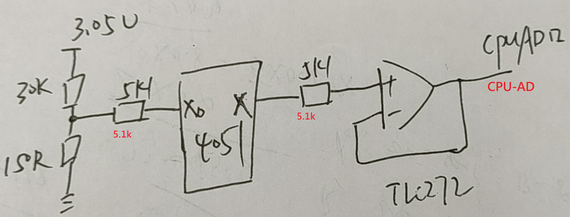
The circuit diagram as below:


thanks.
  • Hi Wu,

    what is the output current of TLC272 when the OPAmp is emitting low level?

    Can you show a schematic?

    Kai

  • Hello Wu,

    Output sinking current does affect VOL. How much output current (consider feedback current too) flows? Figure 18 in the data sheet shows about 100 ohm (100mV/1mA) as typical VOL resistance. The data sheet VOL test doesn't imply a VOL resistance at all with the IOL = 0 setup. The 50mV data sheet max is a bit odd with no current flow.

  • Hi Kai,

               Circuit is update, please refer to the post.

    thanks.

  • HI,

         the output current about 1-2uA .

        For CPU's AD interface.


    thanks.

  • Hi Wu,

    take care, to assure that the output MOSFET goes into hard saturation, VOL at IOL=0A is specified for VID=-0.1V (differential input voltage) and for VIC=0.5V (common mode input voltage). With a much smaller VID or even a positive VID the input offset voltage of OPAmp can prevent the output stage from going into hard saturation. Then, the output resistance can considerably increase. This can cause a higher VOL, if the ADC injects a dynamic current into the output of TLC272 during conversion.

    Can you disconnect the ADC input from the output of TLC272? Is the output voltage of TLC272 still higher than expected? Or does it only increase when you connect the ADC input again? Can you also measure the input voltage of TLC272? Is it receiving the correct voltage, at all? Or is the increased offset voltage you observe a result of an increased offset voltage of the ADC? And it has nothing to do with the TLC272 itself?

    If an increased input offset voltage of TLC272 is the cause of your problems, you can use the TLC277. I do always use the TLC277 instead of the TLC272, because of it's much lower input offset voltage. I do never use the TLC272.

    By the way, it's not wise to use the full supply voltage range 0V...Vcc when driving an ADC with a single supple OPAmp. Not only, because the OPAmp can never fully reach the rails, but also because no OPAmp behaves very well when you go with the input voltage and output voltage too close the rails. Even the ADC shows an offset error and gain error, making it impossible to handle input voltages which are very close to the rails. Because of this I always use a limited range of let's say 0.1V...Vcc-0.1V. The appropriate range depends on the used OPAmp and ADC, of course.

    Kai

  • Wu,

    It is common to place a R C low pass filter between the op amp and the ADC converter. The capacitor holds the voltage during the ADC sample current pulse. The resistor separates the op amp from the capacitor to prevent instability (creates a zero in the load).