This thread has been locked.

If you have a related question, please click the "Ask a related question" button in the top right corner. The newly created question will be automatically linked to this question.

LM397: LM397

Part Number: LM397

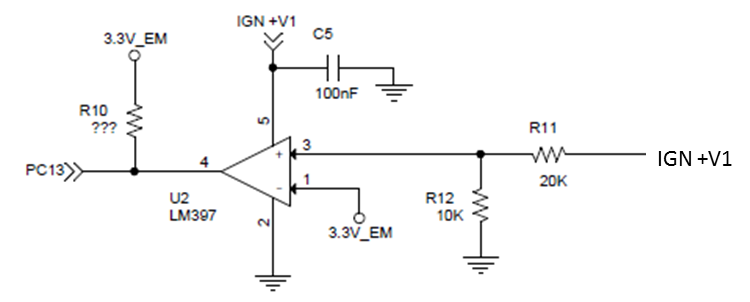
I am currently using LM397 and the functionality I want is the following.

1] IGN + V1 can have three possibilities, namely, 0V, 12V or 24 Volts.

2] The circuit is expected to give the output either 0 Volts or 3.3Volts.

3] When Pin number 3 (+ input) has voltage less than 3.3V (applied at –ve input)  or for that matter any other reference voltage, then I should get 0 Volts.

4] When Pin number 3 has voltage more than the reference voltage, I should get 3.3 Volts.

5] LM397 is an open drain op-amp for me to get the required logic level of 3.3 Volts.

6] Current issue is that the circuit is performing well in all the conditions except when IGN +V1 is 0 volts. In this scenario, when IGN +V1 is 0 volts, it is applied to Pin number 5 and also the positive input, and I am getting 3.3 Volts as output. I expect to see 0Volts and not 3.3 Volts.

7] I need a circuit in which the output of Op-amp is 3.3 Volts when Pin 3 has more voltage than Pin 2, i.e. IGN + V1 is either 12 Volts or 24 Volts, and the output of op-amp is 0 Volts when Pin 3 has 0 volts and IGN +V1 at Pin 5 is 0 volts.

8] Kindly suggest the appropriate circuit and op-amp.  Can you please tell me where I am makign a mistake?

  • Abhijit

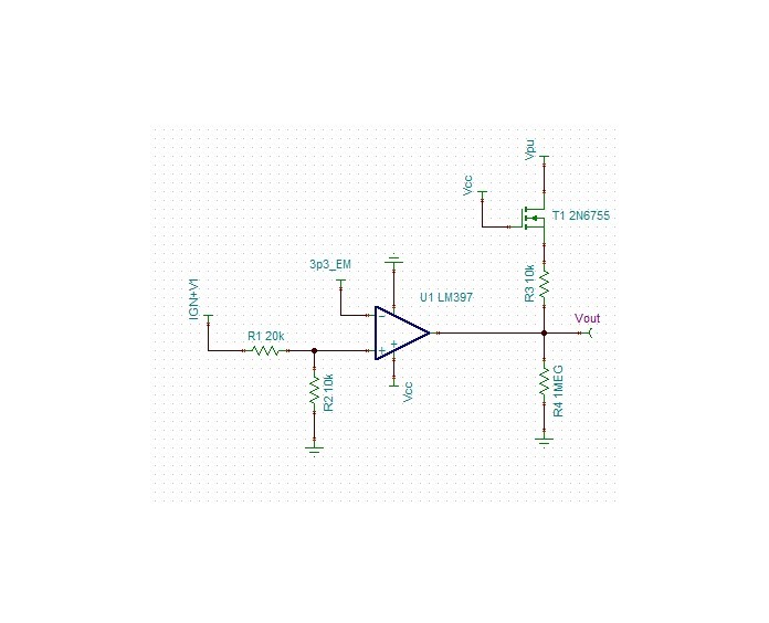
    Unfortunately, when the power supply to the comparator is 0V, there is nothing to actively hold the output low.  So the output will be pulled high by the pullup resistor.  Therefore, if you want to achieve your condition of output low when the power supply is 0V, external circuitry will need to be added.  One way to accomplish this is to put an n-ch MOSFET in series with the pullup resistor and add a pull down resistor on the output of the comparator.  The gate of the MOSFET is driven by the power supply of the comparator.  When the power supply is greater than 3.3V plus the threshold voltage of the MOSFET, the output will be pulled high.  you mentioned that IGN+V1 is either 0, 12, or 24V.  So this solution will work at those discrete values.  However, at IGN+V1 values lower than 3.3V+VT, the output will be held low by the pull down resistor.  The solution would look something like this.

    Chuck

  • Hi Chuck,

    Thanks for a quick reply. I just want to confirm from you if if this circuit will work in the following scenarios.

    1] The circuit requires always the following condition, i.e.  IGN+V1 = Vcc. That means IGN+V1=Vcc will either be 0V or 12V or 24V.

    2] I am assuming that Vpu is 3.3 Volts. Is this correct? I need 3.3 Volts to match the microcontrollers voltage level.

    3] Are you suggesting that the Gate of the MOSFET should be driven by IGN+V1=Vcc supply to it? Thus, when Vcc is less than 3.3V + threshold of the MOSFET, the output of the op-amp will be zero. This would be the case when one of the discrete levels that is 0 volts is applied to both the power supply of the op-amp as well as to the gate of the MOSFET.

    Finally, thanks a lot of a great support. I really appreciate you doing the simulations and suggesting me the modification to the circuit.

    regards,

    Abhijit

  • Abhijit

    Sorry for not providing the simulation file for you to play with.  It is now attached.  That way you can experiment with different options. 

    I also see where I created some confusion for you with my labels.  I have fixed it so the labels match your circuit.  It was a fun little circuit and I got excited :)

    Best of luck on your design.

    Chuck

    LM397.TSC

  • Chuck,

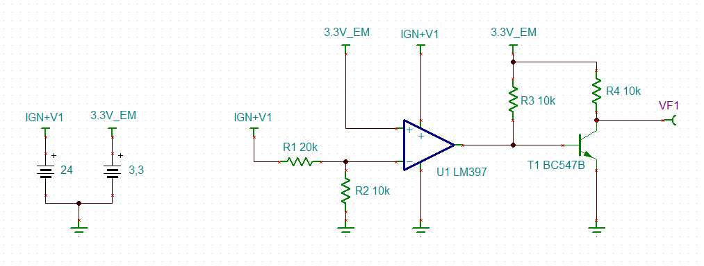
    Thanks for your prompt reply and simulating the design. I used the simulation file you gave me, and modified it a bit, but I am still getting 42.94 mV (~0 volts), when the IGN+V1 = 0 volts. I have taken out the MOSFET and the pull down resistor you added just to check what was wrong with the initial circuit that I used. However, in reality I am getting 3.3 Volts. So may be I am doing some wrong simulation. 

    I am attaching the simulation file and please let me know if there is any issue with my analysis.

    Abhijit

    LM397-1.TSC 

  • Hi Abhijit,

    would this modification do the trick?

    abhijit_lm397.TSC

    Kai

  • Abhijit

    There has not been any response on this thread in a while.  If you still have not resolved the problem, please reply or open a new thread.

    Thanks

    Chuck

  • Hi Abhijit,

    was the modification helpful?

    Kai

  • Abhijit

    Since there has been no further interaction on this thread, I am closing it.  As mentioned previously, if you need any additional support, please open a new thread.

    Thanks

    Chuck