This thread has been locked.

If you have a related question, please click the "Ask a related question" button in the top right corner. The newly created question will be automatically linked to this question.

Unwanted pop-up(prjecting) signal in outptut signal

Part Number: TLV9002
Other Parts Discussed in Thread: TLV2314, OPA2314, TLV9052

Dear,

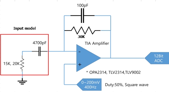
I'm trying to use your TLV9002 instead of OP2314/TLV2314 for our product. Op-amps are used for transimpedance amplifiers. And Both operate by same circuit and operation method. But there is a difference in output waveform. The unwanted pop-up signal does not appear in OP2314.TLV2314's output waveform, but there is the pop-up signal (projecting signal) in TLV9002. Input models are 4700pF-20kohm in serial, or 4700pF-15kohm,or 4700pF-10Kohm in serial. It is connected at negative pin of Op-amp. the pulse(200~500Hz) is applied to positive pin of Op-amp. When using TLV9002, the pop-up signal appears in 4700pF-20kohm in serial, or 4700pF-15kohm in serial of input model, but not appear in 4700pF-10Kohm of input model. I'd like to know what characteristic differences in op-amp causes this difference and what is the solution. Please see the figure below:
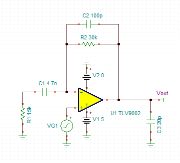
Circuit diagram:

Output signal (input model : 20K – 4700pF in serial)

Thank you,

MG

  • Former Member
    0 Former Member

    Hi MG,

    I spent some time digging into this issue and here's what I've found so far.

    First, I simmed your circuit to see the transient response.  What I saw actually suggested much larger overshoot should be expected.  See images below.  Note that I used 20pF to simulate the input capacitance of the ADC.

    My next suspicion was instability.  However, the phase margin seems healthy at about 77 degrees.  I noticed the capacitance of the "input model" is quite large, so I tried adjusting that next.  Sure enough, decreasing the capacitance of C1 helps things quite a bit.

    I'm thinking that the input model capacitance may not truly be 4700nF for two reasons.  First, the simulation suggests that your overshoot would be much worse.  Also, you'll notice that there is some roll off of the output voltage in the scope shot.  However, the simulation does not show this behavior.  The difference can be explained by the simulation having a much larger input model capacitance, and therefore creating a lower pole RC high-pass filter, than the real world example.

    How did you determine the input model capacitance?

    I still don't think this answers your original question about the slight oscillation of the TLV9002.  Do you happen to have a scope shot of the input signal?  The parts are fairly similar with the OPA2314 having a slightly greater bandwidth.  But again, I don't think instability is the issue here.

    Please let me know your thoughts.

    Regards,

    Daniel

  • Hi MG,

    can you tell more about your application?

    Is there a sensor sitting at the -input of OPamp? Is it connected via a cable (-> cable capacitance!)?

    What ADC do you use (-> capacitive load!)?

    Can you show a scope plot of the input signal as well?

    Kai

  • Hi Daniel,

    Thank you your  efforts to solve the issue.

    First, the input model is just simple modeling for biological analyte to proceed with the test work.. The modeling values are used as the existing values.(beacuse there is no issue when using OPA2314/TLV2314).

    And, input signal is as follows(example).

    200mVpp/400Hz (200~500Hz)

    As your comments, I thinks so TLV9002 is simliar with OPA2314 (except some characteristics like as gain bandwith product, open-loop output impedance..)

    I still haven't figured out which characteristic difference produces this output difference.

    Thank you,

    MG

  • Hi Kia,

    Thank you for considering this issue.

    For the input of Op-amp, there is no cable. the input model is R-C connection in serial(named dummy sensor) for biological analyte.

    And ADC usese SAR techninuqes. For input signal, please see  my replay for fist response above.

    Thank you,

    MG

  • Former Member
    0 Former Member in reply to MG CHOI

    Hello MG,

    I have some follow up questions for you:

    1. Which of the two waveforms is the input?  Is it the yellow or the green signal?

    2. Also, what is the scaling on the y-axis of the image?  Is it 200mV/division for both the yellow and green signals?

    3. Lastly, what supply voltage(s) are you using?  Is it a single-supply?  This is probably less important, but it is good to have this detail.

    Thank you and regards,

    Daniel

  • Hi MG,

    there's a discrepancy in your scope plots: The overshot which Daniel simulated and which you seem to show in the second scope plot (green curve) is absolutely normal and comes from C1. Even an ideal OPAmp would show it as you can see below:

    But in your first scope plots the overshot is missing at all. Or is it unvisible because you have zoomed into the peak? Please always give us complete scope plots which show the horizontal and vertical scalings as well.

    Kai

  • Hello Daniel,

    For your questions,

     1 & 2. The input (400Hz/200mV) is the yellow  (200mV/Div, 2ms/Div) , and the output is the green (500mV/Div, 2ms/Div).

     Then, you don't need to consider this output signal.(That case is just one of outputs )

     3. It is a single supply (2V).

    Thank you,

    MG

  • Hellow Kai,

    For the input signal, at this case, it is 200mV/400Hz as one of input signals ( scale : 200mV/Div, 2ms/Div). And you don't need to consdier the output signal I attached in my previous reply because that case is just one of various cases.

    Thank you,

    MG

  • Hi MG,

    so, the problem is solved?

    Kai

  • Former Member
    0 Former Member in reply to MG CHOI

    Hello MG,

    So where in the circuit is the green signal?  As I understand it, the yellow signal is at the op amp input and the blue is at the op amp output.  Is this correct?

    I would expect the green signal to be the output as Kai has also stated.  The reason why is because, since the feedback capacitor is much smaller than the input capacitor, it will be higher impedance at frequencies where the input capacitor is basically a short.  In other words, there will be a wide frequency range where the feedback capacitor is like an open and the input capacitor is like a virtual short.  In this scenario, you will essentially just see a resistor divider that will gain the input signal up by about 3V/V (a little less in reality).  So, I would expect the green signal to be seen at the output, not the blue signal.

    The most noticeable difference between the parts is that the TLV9002 has a lower bandwidth at 1MHz than the TLV2314 (3MHz) or the TLV9052 (5MHz).  As for what device spec could cause a small wiggle in the blue waveform, I think I still don't understand how the blue waveform is being created to be able to tell.  So, I'm not sure if the lower bandwidth is the cause.

    Can you please confirm where the green signal is coming from?

    Thanks,

    Daniel

  • Hello Kai,

    Unfortunately, I'm still looking for a solution.

    Thank you,

    MGH

  • Hi Mg,

    can you please tell in detail where exactly you need help?

    Kai

  • Former Member
    0 Former Member in reply to MG CHOI

    Hello MG,

    Thanks for the further information.

    The only things I can think of would be a transition in the region of the linear operating region or an aftereffect of a lower bandwidth.  However, I do not think it can be either in this case.  I have discussed it with another member of my team and he is in agreement.

    Do you think this behavior affects your system?  Is it causing issues?

    Have you tried using a different sample in place of the part?

    Regards,

    Daniel

  • Former Member
    0 Former Member in reply to Former Member

    Hello MG,

    Have you been able to try using a different part in the system?

    I have reached out to another colleague to see if they can assist and might know why you are seeing this behavior.  I will reach out again when I have an update.

    Regards,

    Daniel

  • Former Member
    0 Former Member in reply to MG CHOI

    Hello MGH,

    I have spoken to one of my colleagues here and discussed the issue.  In order to diagnose the issue further, I would like to know if you can help me answer the following questions:

    1.  If you increase the value of the feedback resistor, does the problem get better?  I ask this question because by decreasing the input resistance you are essentially increasing the gain of the circuit at certain frequencies.  Similarly, increasing the resistance of the feedback resistor will do the same.  You could try halving the size of the feedback capacitor and doubling the size of the feedback resistor.

    2.  Is this data taken with the ADC connected?  What happens if the ADC is disconnected and instead the output is left open?  What if there is a 10kOhm load, 20kOhm load, or 100kOhm load?

    3.  Can you increase the supply voltage to the op amp and see if the glitch still occurs?

    My colleague is helping me to form a hypothesis about what is causing the issue.  But, I would like to find the answers to these questions before we jump to conclusions.

    Regards,

    Daniel

  • Former Member
    0 Former Member in reply to MG CHOI

    Hello MG,

    I feel that the issue is not yet resolved, but I have not heard back from you in a while.  If you still need help, I suggest you look at the recommendations in my previous message.

    I am going to consider this thread closed unless I hear back from you.

    Regards,

    Daniel

  • Hi MG,

    what exactly is the problem now?

    Kai

  • Former Member
    0 Former Member in reply to kai klaas69

    This thread is now being resolved privately offline.

    Daniel