This thread has been locked.
If you have a related question, please click the "Ask a related question" button in the top right corner. The newly created question will be automatically linked to this question.
Replies: 22
Views: 663
Part Number: TLV6703
Hi Sir
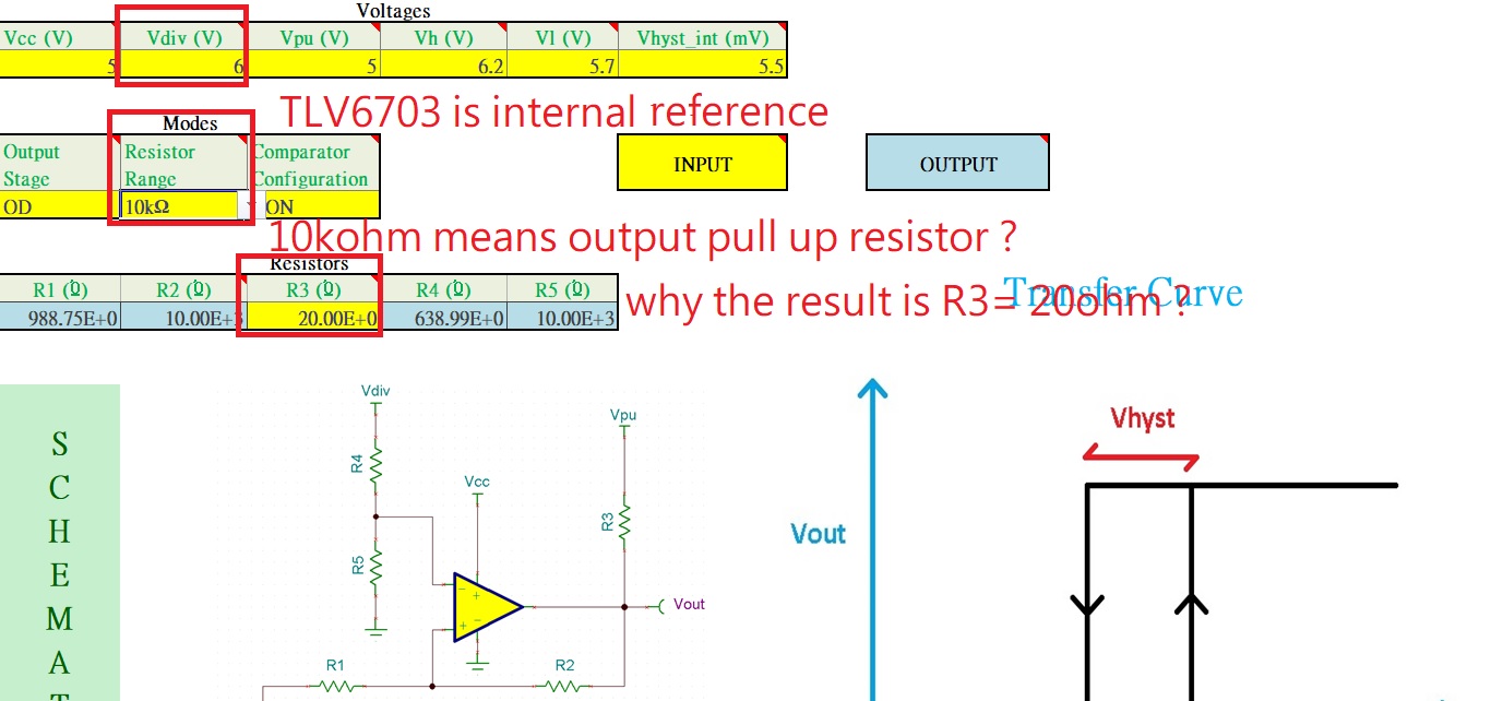
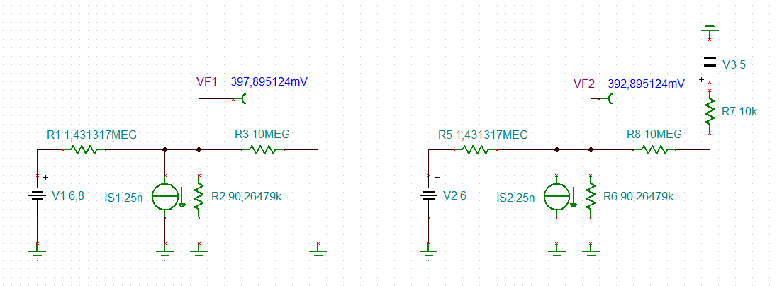
TLV6703 hysteresis range 5.5mV is too small
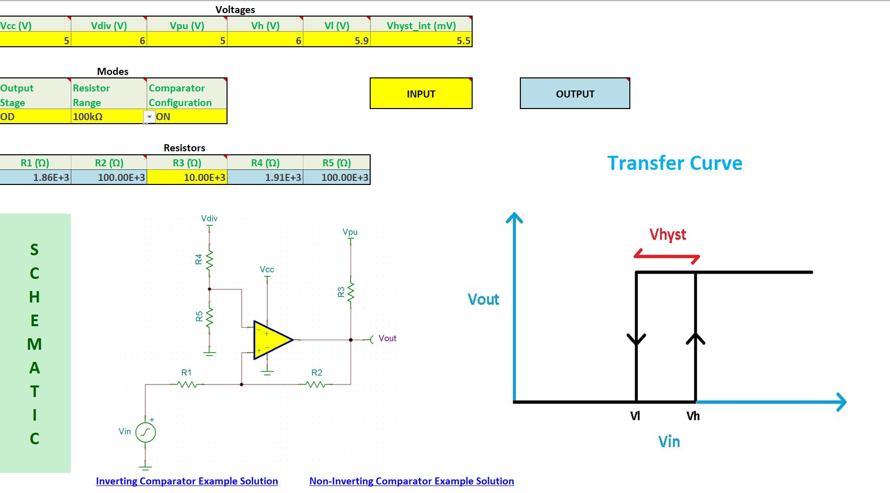
May I know how to extend the hysteresis range of TLV6703 ? have any tool can easy design ?
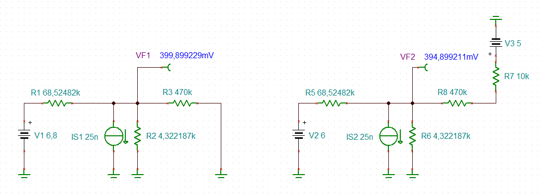
So far our application is 2cell battery voltage monitor ,the battery voltage is 8.4V~6V
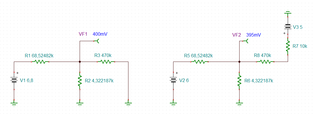
We would like to design VIT-=5.9V and VIT+=6V
Thanks
Hi Kai,
Please see the two cookbooks below about designing external hysteresis for inverting and noninverting configurations:
Non Inverting: http://www.ti.com/lit/an/sboa313a/sboa313a.pdf
Inverting: http://www.ti.com/lit/an/snoa997a/snoa997a.pdf
Regards,
Jonny
can you show a schematic?
Kai
In reply to kai klaas69:
Hi Kai
Thanks for your help
I would like to know how to modify this circuit VIT+ = 6.05V ,VIT- = 5.95V
if have excel calculator ,it will be better
In reply to Kai Hsiao:
Kai,
Please try this excel tool for calculating hysteresis. I'm not sure what your output high level was in this case so I wasn't able to test it out first. Please let me know if you have any feedback on the tool!
JonnyComparator Hysteresis Tool.xlsx
In reply to Jonathan Nguyen:
Hi Jonny
Thanks for your reply and tool
I use the tool to calculator ,it is weird
1. TLV6703 is internal reference ,my condition is below ,if I set the Vdiv voltage under 5V ,it will have warning information
2. Resistor range I set 10khom , but R3 result is 20ohm ,which one is correct
So far our schematic is using TLV6703 (internal reference) ,could you help to double confirm how to use TLV6703
R3 is an input (in yellow), so the default that had showed up was 20 ohms. You can change that to whatever value you plan to use for your pullup. From there, the "resistor range" tab will calculate the remaining resistors as close to the range you select.
Did you want your VIT+ at 6V or 6.2V? I see in the screenshot you provided, you have Vh set at 6.2 and Vl set at 5.7, which is different from your initial post.
Because the part has internal reference, you can ignore whatever values it generates for R4 and R5 - I believe R4 is the trouble maker for your case that is causing the warning to show up. Changing Vdiv to less than 6V doesnt change the values it calculated for R1, R2, and R3. Thank you for the feedback and I will look into this... not sure why it is throwing out a warning for this case.
Below was what I was able to verify to work for the part:
We have not seen any response on this thread in a while, so I am going to close the post. if you require further assistance, please reply or open a new thread.
Chuck
In reply to Chuck Sins:
Hi Chuck
OK
We will check your suggestion
unfortunately, the PSPICE model of TLV6703 cannot be imported into TINA-TI. So, I made a simplified TINA-TI simulation:
This means the following: In your schematic choose R58 = 33k + 910R, R59 = 2k4 and solder a 10M resistor from the "sense" input (pin 3) of TLV6703 to the output (pin 1) of TLV6703.
To be able to compensate for the manufacturing tolerances of resistors and threshold voltages of TLV6703, you could use a 2k precision multiturn cermet trimmer instead of the 910R resistor.
Thanks for your fully support
Is it possible to provide the excel calculator to us ? due to we may change the VDD and pull up voltage and hys voltage range
it will be easy to use TLV6703