This thread has been locked.

If you have a related question, please click the "Ask a related question" button in the top right corner. The newly created question will be automatically linked to this question.

INA139: INA139 design solution in brick power module for prevent current backflow

Part Number: INA139

Dear colleague,

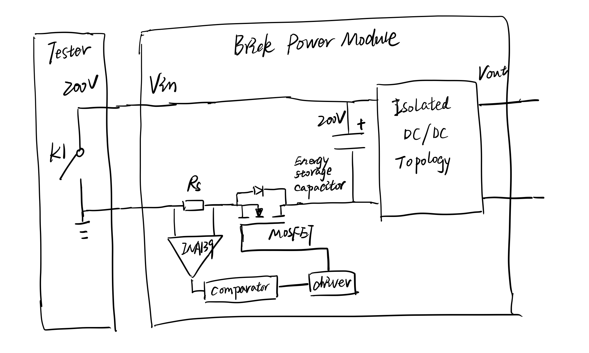
Our customer is planning to do a design in the brick power module for preventing current backflow. The previous solution is a diode, but as the power rate increases, a diode has more power dissipation. So we want to use this solution as the below picture. Why we need this function is because of tester special feature.

In normal mode, the tester provides DC voltage to the brick power module, max DC input is 200V.

In special mode, tester will act like short(K1 close), but at this moment, the energy storage capacitor has 200V voltage, if we don't prevent current backflow, it will happen short circuit and fail the test.

This may be a brick power industry standard, so if we could provide a solution, it will be significative.

So could you please reply to our 2 questions?

1. Whether the function is feasible?

2. How to calculate the detection speed? Customers want it as fast as possible.

Best Regards,

Rock Su

  • Hello Rock,

    Can you use double pole double throw relay or solid stay relay to turn on or break only one state of the power line can be engaged? The attached detection circuit may be too slow for the event. 

    Regards, Raymond

  • Hi Rock,

    In theory this should work. A couple of additional points to consider however: (1) The MOSFET needs to be reversed otherwise current won’t be blocked as drawn. (2) The comparator has to be a latched one.

    Ideally, the delay would consist mainly of the settling time of INA39, and propagation of the comparator driving the MOSFET. However, because the INA139  (any amplifier for that matter) is likely saturated during normal operation of the “tester”, there is going to be an additional saturation recovery delay. A bidirectional current sense amplifier can alleviate this but it may bring with it other design challenges.

    Whichever you choose, once the design is somewhat firm, a simulation can be run to check the delay more closely.

    Regards, Guang

  • Hi Raymond,

    Do you have another solution?

    Thanks a lot!

  • Hi Rock,

    Since inserting a forward diode method was working, you may replace the forward diode with P-Mosfet. Use K1 switch to control the Gate of P-Mosfet. This will work similarly as forward diode, except you has a lot less heat dissipation across the DS terminal. This is as simple as the forward diode solution. 

    Regards,

    Raymond

  • Hi Raymond,

    K1 is an equivalent switch, the customer can't use it, because it belongs to the tester.

    Thanks a lot!

  • Hi Rock,

    If you place a resistor or light bulb in parallel and next to 200V input capacitor, it may discharge capacitor quickly, when power is disengaged. This method may or may not work. It will require experimenting a bit, since I do not know the output impedance of the tester in open circuit. The parallel resistor has to be less than the open circuit impedance of the tester. 

    Regards,

    Raymond

  • Hi Rock,

    Have you tried industrial grade surge protector in front of DC/DC converter? The fancier one may have the features you want. Raymond