This thread has been locked.

If you have a related question, please click the "Ask a related question" button in the top right corner. The newly created question will be automatically linked to this question.

OPA388: weird behaviour with large signals

Part Number: OPA388
Other Parts Discussed in Thread: OPA340

Hello,

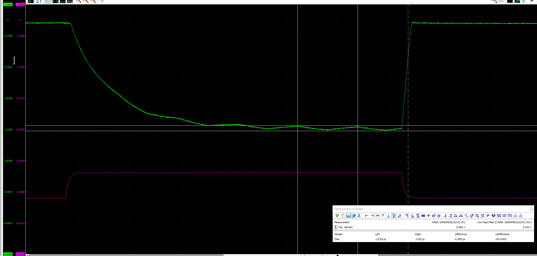
OPA388 behaviour measured with following. IN+ is connected to adjustable voltage to set output voltage level. 

Settling is correct when output voltage starts from linear region ie. output is below 3V (+margin). Green is output and violet is IN.

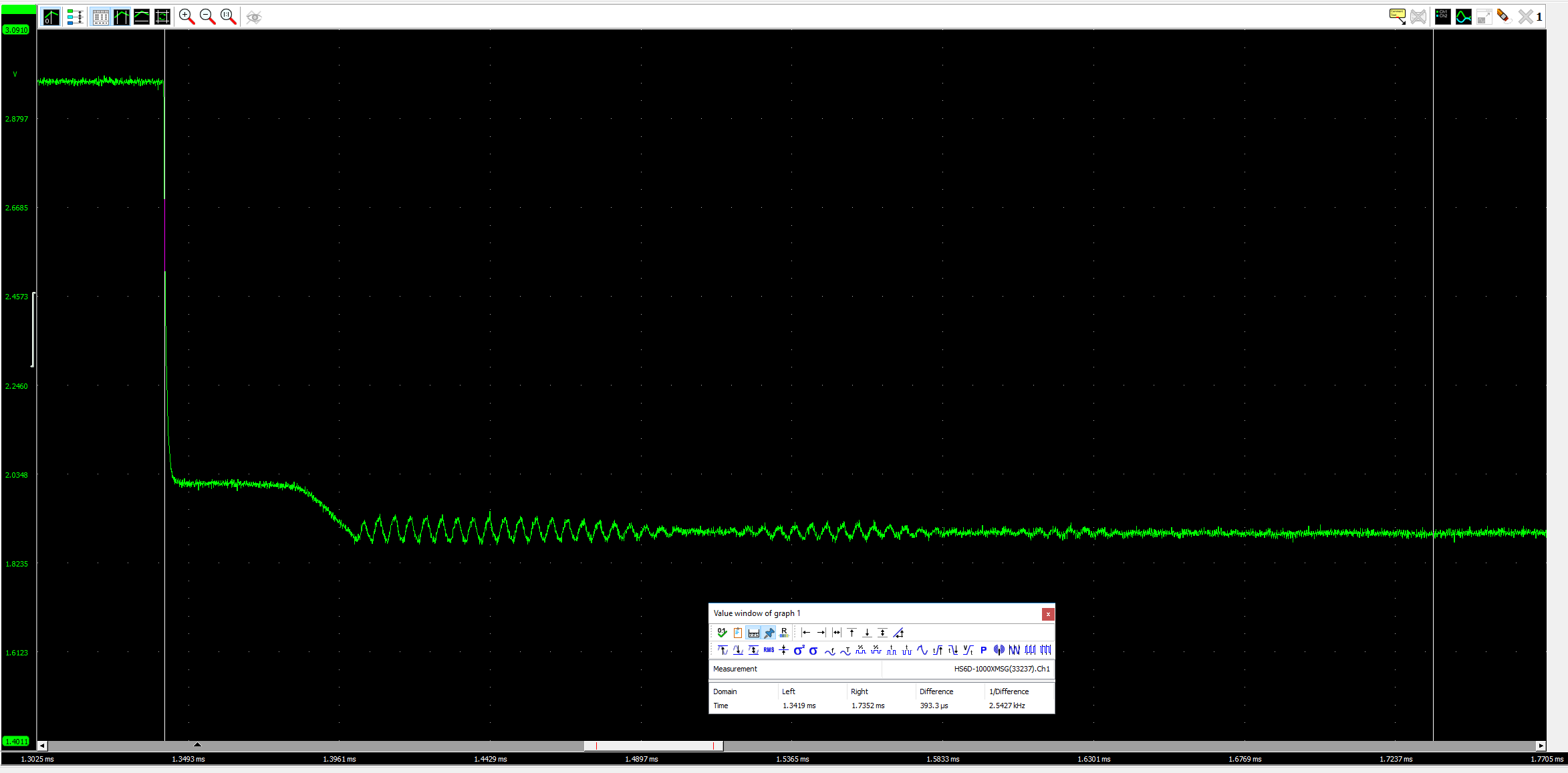
Weird behaviour starts when output voltage is adjusted to start from 3V.

And behavior seems to be different when adjusting pulse time and output voltage DC level.

There seems to be ~140kHz oscillation in large step signal response. Could you explain why this is happening? And how oscillation behaviour could be prevented?

  • Hi user,

    what are the exact input voltages at "IN"? I can't decipher from your scope plots.

    And what is the time scale on the horizontal axis?

    What is driving the inputs "IN" and "V_OP2". How long is the wiring at these inputs?

    And where do you connect the scope probe to measure the output signal? On the left side of R9? Or on the right side?

    By the way, what scope probe do you use? 1:1 or 10:1? What about the probe capacitance?

    Is C11 directly sitting at the pins of OPA388?

    Kai

  • Hello Kai,

    I varied input voltages so that DC is 0.25V or 0.7V. Amplitude also varied 40 to 60mV. No difference in behavior.

    You can click on pictures to get more zoom, timescale varies on plots. See difference between markers. First picture it is 17us -> scale is 10us.

    Signal generator is driving IN. V_OP2 is resistor divider from 3V so that resistor to GND is potentiometer. Parallel to potentiometer is 10nF cap.

    Measuring on right side of R9 ie isolating opamp from probe. Probe is 10:1 and capacitance 17pF.

    C11 is about 4mm distance from pin. No difference if I remove C11.

    Here is one more plot with horizontal scale visible and markers for IN.

     -Petteri

  • Hi Petteri, 

    Thank you for clarifying a few points, per Kai's questions. 

    Looking at the datasheet, the overload recovery is defined when output is at the supply level (VIN × G = VS), and the typical value is 10 us. If I run a simulation of your setup while keeping Vout <= Vs, I get about ~20 us, which matches your results pretty closely in the first scenario shown above. 

    As you start to exceed the supply voltage on the output, parasitic capacitances and inductances become relevant. The simulation show that the overload recovery time increases as you increase Vin x G beyond the Vs, but doesn't account for the odd looking ringing effect you're seeing. 

    That leads me to believe that there might be something external to the op-amp that's causing this effect. Could you tell me if you're doing this on a proto board or a breadboard, or whether you have a PCB for the circuit you've shown in your original post? In case you have a PCB, would you mind sharing the layout? 

    I look forward to hearing from you. 

    Regards,
    Vladimir

  • Hello Vladimir,

    You are measuring settling time in your simulation, not overload recovery time. Here is some pictures for overload recovery time.

    From positive side recovery time is less than 1us.

    From negative supply it is larger, almost 2us.

    Recovery time is internal stages to be able to recover from saturation situation. In overload or recovery situation output stays at supply level.

    I changed C14 to 4pF and settling is much faster, 3us. Just you to see that your simulation is about settling time, not recovery time.

    Here is layout.

    2 layer PCB. No issues here I would say.

    BR,

     -Petteri

  • Hello.

    I changed OPA388 to OPA340. Here is plot.

    Oscillation and odd behavior seen also in OPA340 settling. What is happening? Is this normal to all opamps?

    BR,

     -Petteri

  • Hello,

    update once again. Sorry for many replys but to give you more information. I changed OPA376A and then settling is as expected.

    Would be interesting to understand rootcause for oscillation seen with OPA388 and OPA340.

    BR,

     -Petteri

  • Hi Petteri,

    unfortunately, you don't specify the voltage V_OP2. With a zero-drift OPAmp you must always guarantee that the+input and the -input of OPAmp are at the same potential. Is this the case in your measurements?

    Kai

  • Hello Kai,

    added V_OP2 in red with OPA376A. Gain is not changed and thus same voltage levels also with OPA388 and OPA340.

    Opamp to switch output to ~middle between VDD and GND then inputs has to be close each other as gain is 40.

    BR,

     -Petteri

  • Hi Petteri, 

    Interesting results. I'm at a loss as to why there would be an issue with OPA388 and OPA340 but not with OPA376A. The first two devices have completely different topologies (zero drift vs traditional CMOS), so I'm surprised that both show a similar phenomenon on the output. 

    Let me check with more senior engineers in the team to see if there's something I'm missing, and I'll get back to you.  


    Regards,
    Vladimir

  • If you zoom out in time, does the oscillation on the OPA388 sustain itself or quit like the OPA340?

    Can you do an experiment?  Change the gain from -40V/V to say -20V/V and see whether the frequency changes.  145k is close to our internal autocorrection circuitry clock rate, so I'd like to differentiate if it could be related to that, or the overall loop response of the amplifier (hence gain change).  

    I am slightly suspicious of two other things.

    1. Can you comment more on C11?  What type of capacitor is it?  Ceramic COG/NOP?  

    2. The layout has quite a bit of cap to the inverting input.  The inverting input appears to be surrounded by ground as well as a pour underneath.  One more experiment to see if input capacitance is an issue would be to increase the feedback capacitor by a decade (200pF). 

    Thanks,
    Scott  

  • OPA388 oscillation seems to sustain.

    Here is 20V/V gain plot.

    These are done with following schematics. In 20V/V 200k changed to 100k. Cf in parallel with 200k is 4pF.

    C11 = 0402YD104KAT2A. I have tried with capacitor and without. No change in behavior.

    I would say inverting input cap is quite small. It should not effect to this. Board is 1.6mm thick -> beneath GND plane is quite far and cap is small. From trace cap to parallel GND plane is small. And if I change Rf cap to 200pF then pole comes to so small freq that settling changes totally.

    BR,

     -Petteri

  • Petteri,

    The fact that the 'oscillation' frequency didn't change with the altered loop points towards a part behavior.  I talked to the IC design team and you may very well be seeing a behavior they'd expect from a chopper amplifier.  Can you repeat your experiment but zoom out to >1ms to see if the ripple goes away?  When the output is railed the inputs are pulled apart and a large [relative term here] voltage is stored on a large [relative term here] internal capacitor.  It takes a long sequence of autocorrection functions to zero this back out.  It's a pretty similar behavior to when the part startups up when powered on, and could take as much as 500us to come into proper regulation.  We often discourage choppers to be used as open-loop comparators for some related reasons.  They're simply not happy with their inputs more than a few uV apart from each other, and can only seamlessly handle the quick transient condition caused by a slew condition.  

    Thanks,
    Scott

  • Hi Petteri, 

    Have you had a chance to try the latest suggestion from Scott? Please let us know whether Scott's explanation of the ringing phenomenon was sufficient, or if there are further questions. 

    Regards,
    Vladimir

  • Hi Petteri,

    I think it has to do with your setup. Your layout looks strange to me.

    Why is the right of R17 ending in the nowhere? How and where do you connect the "IN" signal? The same with the "V_OP2" signal. I don't see the 10nF cap (and the voltage divider) mounted very close to the +input of OPAmp.

    I suspect that you have some cabling at these two inputs? This is deadly with a chopper OPAmp! A chopper OPAmp can do magic, but you must handle it properly. It needs very short connections at the inputs and needs a low impedance at the +input, especially at higher frequencies. See also section 10.1 of datasheet of OPA388.

    So, please improve your setup. Increase the 10nF cap to 100nF, or even more, and mount it as close as possible from the +input to signal ground. And avoid every cabling at the inputs!

    By the way, a chopper OPAmp isn't normally used to handle input signal with fast edges. That's not what the high bandwidth of the OPA388 is used for. The high bandwidth of the OPA388 rather allows to provide enough linearizing loop gain when using a high closed loop gain. See figure 9 of datasheet.

    Kai

  • Hello,

    here is plot for OPA388 longer settling.

    So it takes at least 400us to settle.

    My setup has some other circuits and thus layout is looking weird. But I don't think it is layout issue. Traces are not so long and opamp having GBW 10MHz should not be so sensitive to trace inductances. (also phase margin at 10MHz is 90degrees -> lot of margin to oscillation). You can see from pictures what I have inserted that amplifier is stable having very nice settling when it is not overdriven.

    And I have tried inserting 10nF cap directly to + pin, no chages.

    So I would say overload condition causes issue. And I would say TI should replicate what I am seeing on your boards.

    And one point is that specification is not clear at all if OPA388 can not be overdriven.

    ------

    Another issue is that OPA340 which is traditional opamp is having also weird behavior. Comments to that?

     -Petteri

  • Hi Petteri,

    Being a building block device, op-amps find their way into all sorts of applications, configurations, railing scenarios, etc -- and we simply cannot describe all permutations in a datasheet.  At times customers even show us behaviors we didn't know about, as even our characterization/validation scenarios are bounded.  As customers do discover nuances with devices, we try to feed that back into our new product development team to watch out for these gotchas on new devices.  

    We do try to encourage customers to stay in the linear operating region via clamping, etc, or else sometimes "odd" behaviors can be encountered.  Choppers tend to have a few more of these behaviors due to their mixed signal nature.  

    Your measurement of 400us seems to well correlate to the behavior the design team suspected.  However, the fact that you say the same behavior exists on an OPA340 does not.  You see the same type of time scale for settling out?  Can you provide pictures of the OPA340 settling?  aka is it traditional ringing decaying with time?

    Thanks,
    Scott

  • Hi Petteri,

    the fact that the OPA340 is showing the same weird behaviour proves that it has to do with your setup and/or layout! Even the scope plot of OPA376A is showing small HF noise peaks. And if you look carefully at the last scope plots of OPA388, you will see a beat which means that two HF signals of different frequencies superimpose each other. 

    Kai

  • Hello Kai and Scott,

    I have little bit different opinion on spec. I would hope as customer if part is known to have some limitations that it would be mentioned in spec. Was it Kai who pointed out at that chopper is expected to have very little delta in input signals to operate correctly ie. not to overdrive amplifier. And if this limitation is known from design phase it should be mentioned in spec.

    And for layout. I really don't believe this is layout issue. I have tested many opamps and most of them have no issues. For example OPA376A works correctly from TI. HF peaks are due to oscilloscope noise.

    Here is plot for OPA340. Oscillation is not always present when overdriven.

    BR,

     -Petteri

  • Hi Petteri,

    can you show a photo of your setup?

    Kai