This thread has been locked.

If you have a related question, please click the "Ask a related question" button in the top right corner. The newly created question will be automatically linked to this question.

INA168: Transient spike at turn on

Part Number: INA168
Other Parts Discussed in Thread: TINA-TI, INA193

We are using this to monitor the current in a battery system.  This is a unique battery that is "triggered" to provide voltage, i.e., it is not on all the time and switched on and off.

We are powering the INA168 from a 5 V supply that is always on, as far as we are concerned here.

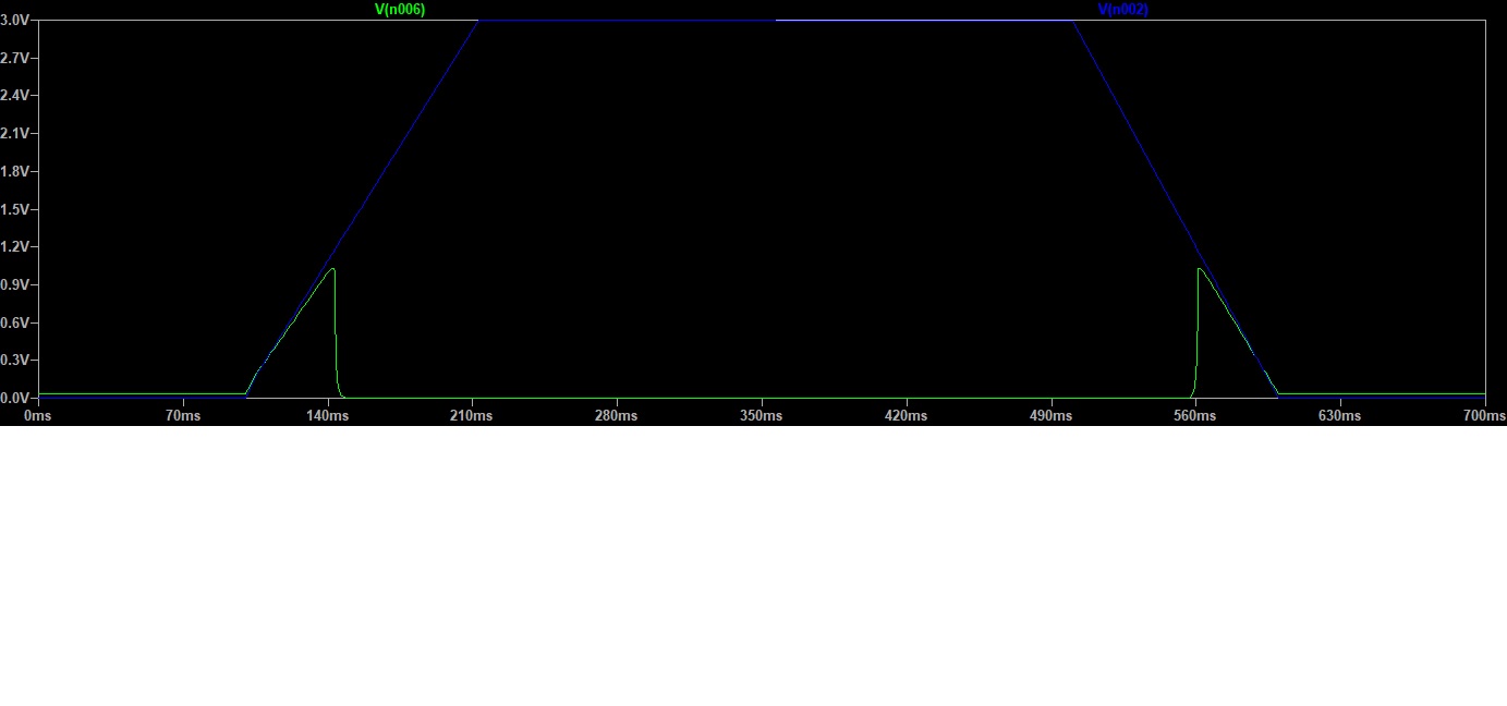
So, when our battery starts to ramp up we are seeing a spike on the output voltage. I can't share data from the system, but I can show the SPICE model which does the same thing.

Is this normal? What exactly is happening here? Is there a way to suppress it? Note that it happens even if the current sense and 1K isolation resistors are removed.

In the voltage plot, the "battery" voltage is blue and the output of the INA168 is green.

  • Hey Keith,

    My apologies for the delayed response. 

    I am seeing the same thing in my TINA simulation, although I cannot determine where exactly the rise in output current is coming from. I do not see input bias current going into IN+ pin, which is where current flows into to create the sense voltage, nor do I see some rise in the input sense voltage.

    Ultimately I believe this is due to the circuit operating outside of its specified range. So for the time that VCM (input common-mode voltage) is less than 2.7-V, the device is operating outside of its specified operating condition. Thus, there might be circuits inside the device not turning on and internal nodes floating with VCM causing output current to rise until it is close to 2.7-V. At this point the internal amplifier can correct this and part will work normally.

    If you are disconnecting the inputs from the battery rail, this is also outside of operating region and might actually put the device into an undefined state. So if VCM is floating, then the same internal nodes might not be turning on and thus parts exhibits the problem. I would assume this problem gets worse if the inputs pins are not even connected to each other.

    Considering this happens with the model (which is a transistor-level model), I am fairly confident that this is expected behavior of the device. The company is on Holiday, so I will need to consult with colleagues during normal business hours on Monday December 2nd, at which point and I can try to confirm this behavior.

    To suppress maybe a capacitors across R8 could help, but this could be really difficult considering how slow the VCM ramp is. Inserting some blanking time to negate the output until device is in normal operating conditions is the best practice here.

    Sincerely,

    Peter Iliya

  • Thanks, I kind of suspected some sort of common mode thing, As long as we can describe it properly, we are probably OK. Just to let you know, this is what wikipedia calls a "molten salt battery" so we are watching it ramp up as it fires.

  • Hi Keith,

    you could bias the ground pin of INA168 with a bias voltage of -3V, as shown in the following TINA-TI simulations. This would guarantee that the common mode input voltage range of INA168 is never violated in your application:

    Of course, you would need to substract the bias voltage from the output signal afterwards.

    keith_ina168.TSC

    Kai

  • Thanks, but this design is pretty well fixed. I also don't think we need accurate currents below Vin of 3 V.

    I would have expected that some of this would be mitigated by using a separate supply for V+ (At least I bet that this is what the designers thought!).

  • We used to use an INA193 in this design, but switched because of the lower bias current.

    I see that the Common Mode range is in the "Electrical Characteristics" of the INA193 but only in the "Recommended Operating Conditions" of the INA168.

    Being a data sheet language lawyer, that means that it is a much more ambiguous specification for the INA168, or not really a spec at all. Was there a reason for the change?

  • Hey Keith,

    This is not how the datasheet should be interpreted. 

    INA168 datasheet mentions the Recommended common-mode voltage range (section 6.3) and the same characterized common-mode voltages (VCM) range in the Electrical Characteristics (EC) Table (section 6.5). In the EC table, common-mode rejection (CMR) is specified at 100 dB minimum from 2.7V to 60V,  which is a pretty clear indication of operation and performance for the entire VCM range of the INA168.

    The INA193 is a completely different device and architecture and thus the datasheet is framed differently. While it has larger Absolute Maximum and operating VCM ranges, the performance varies in different regions of the VCM range. This is why we don't list the entire VCM range in the recommended conditions table (section 7.3) of INA193 datasheet. Certain INA193 specs are tested under different VCM condition in the EC table to elucidate the difference in performance.

    Hope this helps.

    Best,

    Peter

  • Thanks, I think this can be put to bed.