This thread has been locked.

If you have a related question, please click the "Ask a related question" button in the top right corner. The newly created question will be automatically linked to this question.

AMC1100: AMC1100

Part Number: AMC1100
Other Parts Discussed in Thread: TINA-TI, AMC1311

Hi 

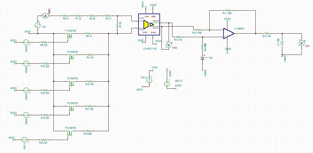
While simulating AMC1100 part on TINA software for controlling my input current following things were observed.


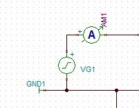
  1. Without AMC1100 part connected, on controlling the ON/OFF of the MOSFET, I am able to control the current in the path with the simulated current is equal to theoretical current (shown in Fig 1 and 2)
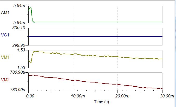
  2. With AMC1100 part connected, on controlling the ON/OFF of the MOSFET, the simulated current is not equal to theoretical current (shown in Fig 3 and 4)


It should not happen as the current drawn by AMC1100 is very low as specified in the datasheet.


Kindly let me know the reason for that.


  • Hi Manish,

    please share your TINA-TI file with us.

    Kai

  • Hi Manish,

    Please send along your TINA file as it is hard to make out some of the resistor values in your screen captures.  If I understand your schematic correctly, you are trying to switch in/out different resistors in the bottom of a voltage divider string.  It looks to me like you are going to exceed the common-mode operating range of the AMC1100 (which is VDD1 MAX) as well as the analog input voltage range (which is +/-250mV).

  • Hi,

    attached is the TINA file.

    What i want is to control the input current by switching different resistor using MOSFET. min current needed is 1.0mA (at 10V DC)and max it can go to 3mA( at 300V AC/DC).

    I can choose different set of resistor combination to control the current.

    Do i need to put GND1 to the source to control the switching? without giving GND1 to voltage source Can i switch the resistor?

    Do

    TCS_current modified_30112019 - autosave 19-11-30 16_52 - autosave 19-11-30 17_03.TSC

  • Hi,

    attached is the TINA file.

    What i want is to control the input current by switching different resistor using MOSFET. min current needed is 1.0mA (at 10V DC)and max it can go to 3mA( at 300V AC/DC).

    I can choose different set of resistor combination to control the current.

    Do i need to put GND1 to the source to control the switching? without giving GND1 to voltage source Can i switch the resistor? 0160.TCS_current modified_30112019 - autosave 19-11-30 16_52 - autosave 19-11-30 17_03.TSC

  • Hi Manish,

    For the AMC1100 to model correctly, you have to have its voltage source isolated.  Ideally it would be referenced to the junction of R2/R5, R4, R15...  All of those resistors to the transistors would have high voltage across them, plus there would be some leakage current to deal with.  You would still have too more voltage across R22.then the AMC1100 has input range.  The AMC1211 might be the better option since it has a higher input voltage range.

  • Tried with AMC1311 also.

    Can you please share the schematic of the design that meets my reuirement.

    Regards

    Manish Sharma

  • Hi Manish,

    Your TINA schematic has a sine wave with DC value of 300V and frequency of 0Hz, so it's basically DC.  When you say 300VAC, is that 300V pk-pk or 600Vpk-pk?  Regardless, from the AMC1100 perspective, you only have a +/-250mV input range and you seem to be violating that on 4 of six resistor options.  The CM input range of the AMC1100 is only VDD1, so you'd have to refer GND1 to the bottom of your shunt.  Perhaps different shunt values would give you a wider dynamic range for each current level you want to sample.

  • Hi Tom,

    my input voltage range is for AC and DC. So when i am saying 300V, it could be AC or DC ( if 300V ac is considered then my peak value of sine wave can go upto 425V)

    regarding the resistor values, i can modify them. My concern is only when the system is operative at 10V DC the input current should be 1mA and at 300VAC, the current is 5mA max.

    can you please suggest a schematic(TINA file for the same) indicating the placement of GND1 and GND 2. 

    request you to please provide the same at the earliest.

    Thanks

    Manish 

  • Hi Manish,

    Sorry for the delay - we're all quite busy these days and I really don't have the time to re-design your circuit. 

    If you only have one supply to power the AMC1100 and control all of your transistors, you might consider putting your 'shunt' between the source commons and GND1.  You should probably also consider using solid state relays - something like the Panasonic AQ-H series devices.  You would also need to change R5, R4 and R15 so that you are not violating the ABS MAX input voltage range of the AMC1100.

  • Hi Tom,

    Thanks for your reply.

    As told by you that i am crossing the differential input range of the device (250mV). This is not the case. As when my input voltage chages, i am changing the input path curent and the differential input voltage is 126mV (max)

    Vin R(upper branch) 6000 Differential input voltage (mV)
    R2 22
    10 R3-1 (T1 Mosfet) 1000 31.33010538
    24 R3-2 (T2 Mosfet) 10000 32.9546873
    48 R3-3 (T3 Mosfet) 16000 47.95204795
    110 R3-4 (T4 Mosfet) 33000 62.0162985
    220 R3-5 (T5 Mosfet) 68000 65.38596633
    300 R3-5 (T5 Mosfet) 68000 89.16268136
    424.2 R3-5 (T5 Mosfet) 68000 126.0760315

    with 300 RMS (pk value is 424.4V) the differential input is 126mV.

    I can't use solid state relay in the design.

    I want you to just give me a schematic with MOSFET (controlled by microcontroller with VDD2 and GND 2) controlling the current in input supply (VDD1 and GND1) having interconnection with AMC1100.

    Hoping a positive response from your side.

    Regards

    MAnish Sharma

  • Sorry for the confusion Manish,

    You are violating the VCM input range of the AMC1100 with your configuration.  This is the reason why your model is not working properly as well.  My suggestion to move the shunt to the between the junction of the transistor source connections and GND1 is the best option I have if you plan to control each gate from the same source.