This thread has been locked.

If you have a related question, please click the "Ask a related question" button in the top right corner. The newly created question will be automatically linked to this question.

OPA549-HIREL: OPA549-HIREL

Part Number: OPA549-HIREL
Other Parts Discussed in Thread: OPA549

Dear TI Team,

Greetings!

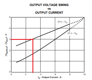
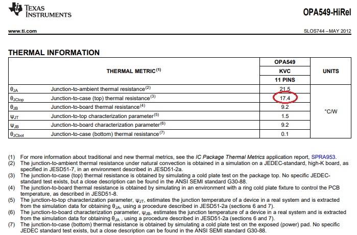
I wish to use OPA549-Hirel (datasheet here, opa549-hirel.pdf in an application to drive the resistive load sinusoidally at 50 kHz (kilohertz) rated 8 Watts at around 4.25 Vrms (Load 8W,4.25 VRMS, 50kHz) with a dual power supply of +/- 6 VDC for OPA549-Hirel configured in Non-Inverting Amplifier mode. I am planning to select this OPA549-Hirel as it is stated that the internal power dissipation can be minimized using minimum possible supply voltage to maintain the required output voltage swing. I request you to give me a straight forward formula with explanatory notes such that I can calculate internal power dissipation for AC loads for OPA549-Hirel. Thanks and Regards, Ajay Chole

  • Ajay,

    It is not clear to me from your description if the resistive load is rated for 8 Watts peak or an average power dissipation, and depending what it is, you must first determine the value of the load, RL, using equation shown below.  

    Assuming that the average power is 8 Watts, you may find RL must be around 2ohms, which means that with the peak output of Vout_peak=4.25*√2=+/-6V and RL connected to ground, the output of OPA549 will require to sink or source a peak current of 3A. Under 3A load, the swing of OPA549 output, Vout, to positive rail is around 3V (see below).  Therefore, in order to avoid clipping of the sinusoidal output you must use a minimum supplies of +/-9V (Vsupply=Vout_peak+3V).

    For more details, please review TI Precision Labs material on Power and Temperature under following link:

    https://training.ti.com/system/files/docs/1160%20-%20Power%20and%20Temperature%20-%20slides.pdf

  • Hi Marek- Thank you very much for your response and the slides. Now it seems I have understood the concept more!

    My power is the active power in Watts- That is, Po=Vorms*Iorms*Cos(phi). Cos(phi), the power factor is 1, one as it is a resistive load.

    Assuming 8W average power, Voutpk is 6V, RL is 2 Ohms, Vcc is 9V (9V as suggested by you). The internal power dissipation Pac_avg as per the formula comes to be 8.19 Watts. And, Pac_max_avg=8.21 Watts. Therefore, similar amount of power compared to output power is dissipated in the OPA549. The heat-sink will have to be designed for absorbing 8.19 Watts??

    Kindly also confirm and explain, the maximum peak-output-voltage obtainable by fixing +12/-12 V power supply and fixing current limit Io_peak=2A. By referring the graph of output swing you showed, i.e V_supply=Vout_peak+2.75V, therefore Voutpeak_max=12-2.75=9.25V. The 2.75V figure I obtained from graph against Io=2A. Is it okay?

    Thanks and Regards,

    -Ajay Chole

  • Yes, the heat sink needs to be efficient enough to keep the junction temperature under 125 deg C (maximum specified in the OPA549 datasheet).  This means that in an ambient 25deg C temperature, the maximum allowable increase in the junction temperature due to power dissipation inside the package may be 100C (125C-25C); thus, the junction-to-board (bottom) thermal resistance must be below 12.2C/W (100C/8.2W). Therefore, you will not be able to achieve the required cooling using the top heat-sink since the junction-to-case (top) thermal resistance is higher than the calculated value (17.4C/W - see below).

    Under peak output current of 2A the maximum peak output voltage, Voutpk, for +/-12V supplies, is 9.25V, resulting in the average power dissipation inside OPA549 package of around 6 watts.

  • Hi Marek,

    Thank you for your response. 8.2W can't be handled by OPA549? Do you mean to say that 8.2W can't be handled by OPA549 alone without heatsink? I am sorry it is not clear to me, please explain again, what is the maximum power that can be dissipated in the OPA549? I mean What's the maximum allowable internal power dissipation in OPA549?  What's the maximum load-power that can be supplied by OPA549? In the Heat Sink Selection Example given in the OPA549 datasheet, a suitable heatsink to dissipate 10W is selected.

    In the second case, limiting the current to 2A, I think for same output average power, the internal dissipation is 6W that is less than 8.2W? Is the second solution that is going with +/-12V better? Kindly confirm. If I go for +/-15V power supply, the situation (power efficiency) will be better??, what will be the peak-voltage achievable for limiting the current to be 1A??

    My rated load voltage can be up to Vo=12V rms [that is Vopeak= 12*sqrt(2)=16.97V]. 

    What is the maximum efficiency that can be achieved for OPA549? It's 70% efficiency for ST Micro's L165 power op-amp (datasheet here,L165_efficiency_given.pdf ). Please give me the maximum efficiency values for OPA549.

    Thanks and Regards,

    -Ajay Chole

  • Ajay,

    That is not what I said -  I said you will not be able to achieve the required cooling using the top heat-sink since the junction-to-case (top) thermal resistance is higher than the calculated value.

    θJA=θJC+θCH+θHA where θJA – junction-to-ambient, θJC – junction-to-case, θCH – junction-to-heatsink, and θHA – heatsink to ambient.

    Since the allowable max θJA is calculated to be 12.2C/W but θJC is already 17.4C/W, this means that in order for the above equation to work θCH+θHA would have to be negative, which is not possible.

    However, you can dissipate 8W in OPA549-HiRel by using the bottom plate since its junction-to-case thermal resistance (bottom thermal pad) is only 0.1C/W - see below. 

  • Hi Marek, thank you for clarification on heat-sink.

    What is the maximum internal power that can be dissipated using both top and bottom heat-sink?

    In the second case, limiting the current to 2A, I think for same output average power, the internal dissipation is 6W that is less than 8.2W? Is the second solution that is going with +/-12V better? Kindly confirm. If I go for +/-15V power supply, the situation (power efficiency) will be better??, what will be the peak-voltage achievable for limiting the current to be 1A??

    My rated load voltage can be up to Vo=12V rms [that is Vopeak= 12*sqrt(2)=16.97V]. Please suggest best possible solution.

    What is the maximum efficiency that can be achieved for OPA549? It's 70% efficiency for ST Micro's L165 power op-amp (datasheet here, 8468.L165_efficiency_given.pdf). Please give me the maximum efficiency values for OPA549.

    Thanks and Regards,

    -Ajay Chole

  • Ajay,

    The power dissipation inside the package is a function of the average output current, Iout, and the differential voltage between Vcc and Vout_rms:

    P_inside_package = Iout*( Vcc - Vout_rms)

    Thus, the higher Vcc for fixed Vout_rms and Iout, the higher power dissipation inside the package.

    You really need to review the material attached in this post.

    Power and Temperature - slides.pdf

  • Hi Marek, thanks for your reply. I am keen to know what is the maximum efficiency that can be obtained for this application and what is the maximum power transfer and dissipation capability of OPA549-Hirel in general. How much maximum power through bottom heatsink can be dissipated?

    Anyways, I will get back to you after Christmas break and will go through the literature you have shared.

    Please do not close this thread.

    Thanks and Regards,

    Ajay Chole