This thread has been locked.

If you have a related question, please click the "Ask a related question" button in the top right corner. The newly created question will be automatically linked to this question.

THS4151: Filter component selection guidance

Part Number: THS4151
Other Parts Discussed in Thread: THS4131, AMC1300, AMC1311, AMC1301

hi,

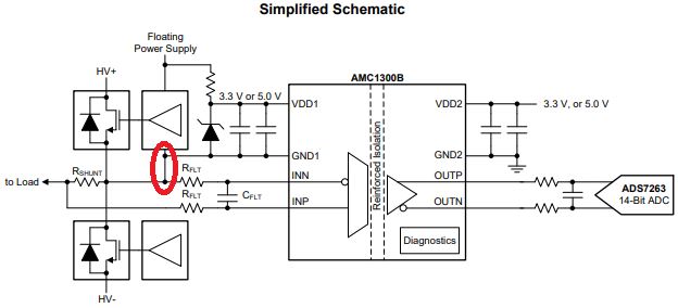
we are designing the amplier for the voltage measurement circuit. AMC1300 is used as isolation amplifier for voltage measurement. Its output is given to THS4131.

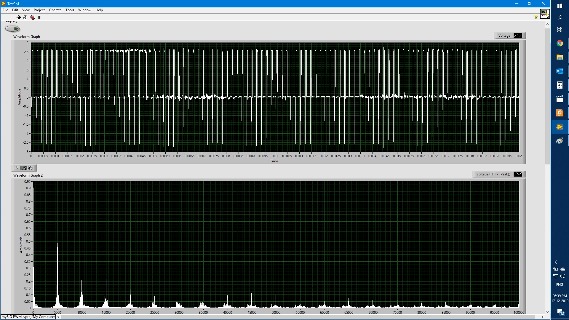
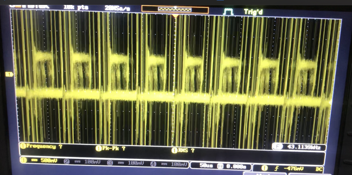
we are facing noise in the amplifier output and the noise signals are in the range of +/-12V. we are guessing that these noise are added into the circuit due to THS4131. 

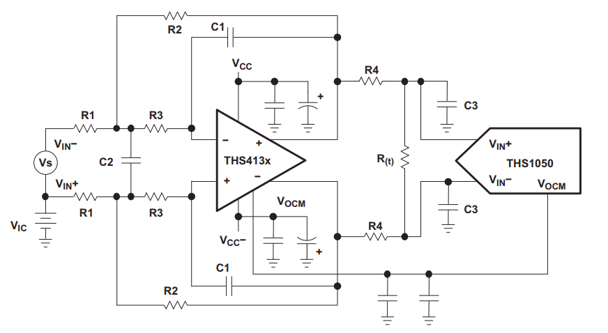
we are trying to add the low pass butterworth filter at the amplifier output as shown in the circtuit below. 

Input voltage to AMC1300 : 75mV

Output voltage from AMC1300 : 615mV

R1 : 402 Ohm

R2 : 4020 Ohm

gain : 10

signal frequency : 15kHz

we ignored the filter components R3, C1,C2, R4 and C3.  we are facing +/-10V noise signal in our output. 

Please guide us to select the values for R3, C1, C2, R4 and C3. 

Thanking you.

Thanks & regards,

Rajasekaran.

  • Hello Rajasekaran,

          R4 and C3 are not part of the filter components which is referenced in the provided Figure 35; instead, they are part of Figure 34 explaining the affects of driving a capacitive load. A isolation resistor, R4, and an active anti-aliasing low-pass filter are important in eliminating the high frequency noise and oscillation that comes with capacitive loading which is commonly seen when interfacing with ADCs. From the provided schematic of your application, there does not appear to an external capacitive load. Would you be able to share scope shots at the output of the isolation amplifier? 

    Thank you,

    Sima


  • hi,

    Now we removed the amplifier THS4131. and AMC1300 isolation amplifier only connected to the circuit.


    In the output of AMC1300, R90 and R92 24 Ohm resistance is connected as load. Please find the attached below waveform & FFT for the inverter output voltage measurement.

    Inverter carrier frequency : 5kHz

    Load : Resistive load

    DC bus voltage : 65V

    Expected voltage accross R91 : 8mV and AMC1300 output is : 65.6mV.

    Kindly guide us to remove the noise in the AMC1300 output.

    Thanking you.

    Thanks & regards,

    Rajasekaran

  • Hello,

    AMC1300 is not the best choice for voltage sensing measurements as the low-input impedance and higher input bias currents will negatively interact with the voltage divider on the input causing large offset and gain errors.

    AMC1311 is optimized for voltage sensing, has high >1GOhm input impedance and is in the same package as the AMC1300.  Can you try the AMC1311?

    That aside, if you'd like us to help debug the current situation more effectively please take differential scope measurements (not digitized labview results) directly at the inputs and outputs of the AMC1300.

  • In addition to Collin's comments, is GND1 (MHV3-) referenced to the input nets VM_B and VDC_0V?

  • hi,

    Today we removed the circuit from high voltage. 

    we applied 4mV at 20kHz sine waveform between VIN_P and VIN_N of AMC1300. we can able to measure the 314mV across OUTH and OUTL of AMC1300.

    Also we can able to measure 3.24V across VOUT+ and VOUT- of THS3141. 

    We can able to observe  the correct functioning of AMC1300 and THS3141 in the circuit. 

    When we applied 24V across DC bus, we can able to get SPWM pulses across  VM_B and VDC_0V. But we test it across R87, R88, R91, R94, R96 we are unable to measure the SPWM pulses. we will verify the same and upate you again. 

    Thanks for your kind support. 

    Thanks & regards,

    Rajasekaran

  • hi, 

    the circuit is, 

    Please find the attached waveform for the AMC1300 output. 

    Click here to play this video

    Please find the THS4131 output waveform.

    We are applying SPWM to the single phase inverter. 

    VM_B and VDC_0V is voltage accross the switch. 

    MHV3- and MHV3+ is separate isolated DC-DC source 

    M5V- and M5V+ is separate isolated DC-DC source

    PS12V- and PS12V+ is separate isolated DC-DC Source. 

    The final output of THS4131, we are getting the noise in the same level of Power supply voltage. Kindly let us know the procedure to eliminate the noise. 

    Thanking you. 

    Thanks & regards,

    Rajasekaran

  • Hi Rajasekaran,

    I'm not able to view the first video, but I can see the second. Can you repost the AMC1300 output video in the same format as the THS output video? 

    MHV3- and MHV3+ must be referred in some way to VM_B and VDC_0V which I do not see on the schematic. This connection marked in red can be made either at the input of the AMC1300B device, or where the isolated power supply is being derived. 

  • hi,

    please find the below waveform for the AMC1300 output.

    Also please find the below attached complete schematic for the inverter voltage and current measurement. 

    converter_v1_0.pdf

    Queries : 

    1) We are using 6 AMC1300B in our project and we are using six isolated power supply for the same. Do we need to connect the VIN and GND1 of each AMC1300B? kindly confirm. 

    2) Shall we connect the GND1 and VIN of AMC1300 in IC Pins directly or do we need to connect before the RC Filter? Kindly confirm. 


    Thanks & regards,

    Rajasekaran. 

  • Hi Rajasekaran,

    Thank you for providing the video. 

    Yes, VINN and GND1 of each AMC1300B should be connected. 

    They should be connected before the RC filter. 

    Please give this a try and let me know the results.

  • hi,

    Thanks for your continuous and kind support to solve our issue. 

    Now we can able to measure the voltage and current without noise issue. 

    Voltage measurement. 

    Current waveform

    Once again thanks for your support 

    Thanks & regards,

    Rajasekaran.

  • Great news Rajasekaran, thank you for letting us know! 

    Please feel free to start a new thread if you have additional questions or concerns. 

  • Dear sir,

    Thanks for your guidance to eleminate the noise in the AMC1300 measurements. 

    When we measure the current signal it works good. 

    When we try to measure the voltage signal, we are getting the constant DC offset. 

    Voltage and current signal measurements when there is no load voltage / current is applied. 

    Yellow - Voltage measurement output. 

    Blue - Current measurement output. 

    we need to measure both AC and DC Voltages. 

    How to remove the DC offset in the voltage measurement circuit of AMC1300. 

    Thanking you. 

    Thanks & regards,

    Rajasekaran

  • Hi Rajasekaran,

    This is most likely due to using a low input impedance device for voltage sensing. There is a bias current flowing out of the both the inputs of the device. The current from the positive input is flowing through the shunt resistor, creating an offset voltage. 

    You can use an implementation similar to what is shown in section 10.2.2 Isolated Voltage Sensing of the AMC1301 datasheet. 

    http://www.ti.com/lit/ds/symlink/amc1301.pdf

    Additionally, you can use this excel calculator to compute the expected error. Simply change the datasheet values in the cells to match the AMC1300.

    https://e2e.ti.com/support/amplifiers/f/14/p/815789/3019110#3019110

  • Dear sir,

    Kindly provide the following details to use the gain and offset error excel calculator.

    1. INL value for AMC1300B.

    2. INL Drift value for the AMC1300B

    3. Rdivider impednace ( Equivalent impedance (Ω) of the resistor divider) : Is it equivalent resistance of Rsense and RIN of AMC1300B ( our Rsense is 1kOhm and RIN for AMC1300B is 19kOhm) The equivalent resistance is : 950 Ohm.

    4. GE Rdivider Drift is calculated as (for 50ppm)  : (100)*50*10^-6 (ppm) * 0.25 * 10^3 (full scale input voltage in mV). what is meaning of 100 in this equation.

    5. Offset error Rdivider (Offset from bias current and divider resistance (Rdivider * Ibias))

    is calculated as "Rdivider impedance x 0.000032 / full scale voltage). what is the meaning of 0.000032 in this equation ?

    6.Offset Rdivider Drift of AMC1300B. 

    Thanks.

    Thanks & regards,

    Rajasekaran

  • Hi Rajasekaran,

    Thank you for your questions. 

    1. This can be found on the first page of the datasheet. It is the same for AMC1300 and AMC1300B. Low Nonlinearity and Drift: 0.03%, 1 ppm/°C (typ)

    2. This can be found on the first page of the datasheet. It is the same for AMC1300 and AMC1300B. Low Nonlinearity and Drift: 0.03%, 1 ppm/°C (typ)

    3. Rdivider impedance (Cell D12) is the size of the sense resistor.  You will have to modify cell D13 to divide D12 by 19000 instead of 18000.

    4. This is the temperature range, 25C to 125C. 125 - 25 = 100

    5. This is the bias current for the input pins of the device. If you take a look at figure 14. you will see that this is dependent on the common-mode input voltage.

    6. This is the drift of the sense resistor.