This thread has been locked.

If you have a related question, please click the "Ask a related question" button in the top right corner. The newly created question will be automatically linked to this question.

INA128: INA128/ Input Impedance

Part Number: INA128
Other Parts Discussed in Thread: INA326, INA828, TEST2

Dear Sir,

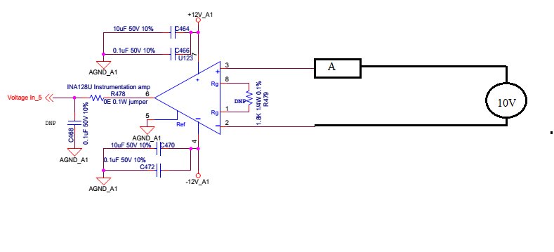
I am using INA128. I want to verify input impedance. As per the datasheet 10^10 ohm || 2pf.  I measured current through ammeter as shown in the attachment. The current is unstable it is varies from 8 uA to 15uA.

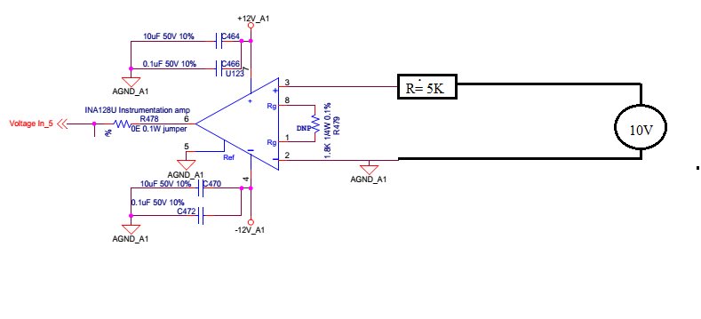
In test 2,  ammeter replaced by 5K resistor and then the voltage difference between with and without resistor 15mV and not stable varies from 7mV to 15mV.

So input resistance around 1M ohm. My requirement is at least 10 M Ohm. Please suggest is it test method has some problem or INA I am unable to conclude. If test method provide test method.

Regards,

Praveen

  • Hi Praveen,

    You can try to make AC measurement. Typically the input impedance is dynamic AC measurement. With this high impedance, you will  need high sensitive test equipment. However, you can get some rough estimate by measuring peak voltage/peak current. 

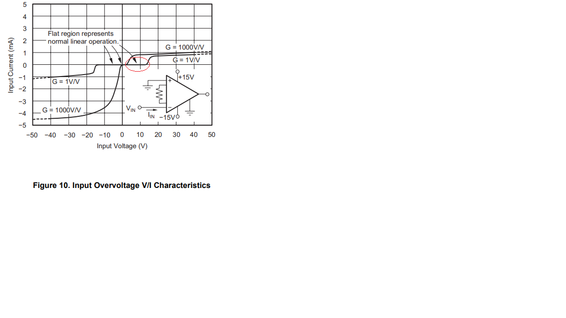
    From the datasheet in Figure 10, you can see the input current is very small and does not show very well in mA vertical scale. 

    Regards,

    Raymond

  • Hi Praveen,

    you have made a mistake. For the input bias currents of INA128 you must provide a path to signal ground. See section 9.2.2.4 of datasheet.

    Kai

  • Hi Praveen,

    I am going to close this inquiry. If you have additional questions, you may open the link again or create a new one. 

    Best,

    Raymond

  • Hi Kai,

    Actually I connected 10 V supply to AGND_A1. Sorry it is my mistake i dint shown in the schematic diagram.

    Regards,

    Praveen kumar M

  • Hi Raymond,

    Sorry for late replay.I was on leave.

    The fig 10 is shown for over voltage protection has current scale of 1mA. The current is in nA, I am  unable figure out anything from this.

    I have a some doubt

    1. when i am connecting INA behaving unstable output is not constant. Changing continuously about 20 mV. Why it is happening.

    2. As you told measure AC output accurately is very difficult with different frequency. Is any characteristics graph for Frequency Vs is available. In data sheet nowhere mentioned Impudence with respect to frequency.

    3. If i am using INA for low frequency signal <1Hz what will be the impedance.

    Regards,

    Praveen Kumar M

  • Hi Praveen,

    The fig 10 is shown for over voltage protection has current scale of 1mA. The current is in nA, I am  unable figure out anything from this.

    I am trying to show the INA128's input impedance is higher than the data you reported. If you divide the data on X-axis (input voltage)/Y-axis(input current) in Figure 10, the input impedance of INA128 is very high, which is consistent with the impedance table reported in its datasheet. 

    1. when i am connecting INA behaving unstable output is not constant. Changing continuously about 20 mV. Why it is happening.


    You placed 0.1uf capacitor at INA128's output, that is the reason why it is unstable. There is a Que, about 33.6dB above the low frequency gain generated from the output capacitor at approx. 62.7kHz. You have to remove the output capacitance or compensate the Que with a zero, see attached Tina simulation. Another pole is also seen at approx. 1MHz. These poles are not present if 0.1uf output capacitor is removed. 

    INA128 01142020.TSC

    2. As you told measure AC output accurately is very difficult with different frequency. Is any characteristics graph for Frequency Vs is available. In data sheet nowhere mentioned Impudence with respect to frequency.


    I do not recall that I made this specific claim. This is legacy product and that is why many of characteristics plots are not present. The newer Op Amp will be able to simulate the input impedance vs. frequency data via Tina model. 

    3. If i am using INA for low frequency signal <1Hz what will be the impedance.


    Please remove the 0.1uf output capacitor and try to measure the impedance again as shown in Figure 10 in DC. In addition, try to make this impedance measurement in a sealed metal can that is shielded via Faraday cage. 


    Since you are interested low frequency signal <1Hz, please take a look at other TI's Instrumental Op Amp Options, such as INA828 and INA326. In the low frequency region, 1/f noise will be a dominated noise factor, and you need to take into account in the circuit design. I am including links, which are parts of noise topics in the op amp (there are total 8 videos in the noise topics). 

    https://training.ti.com/ti-precision-labs-op-amps-noise-lab?context=1139747-1139745-14685-1138803-13847

    Best,

    Raymond


  • Hi Raymond,

    Actually the capacitor is not populated in the board.

    The INA128 is stable if input pins( IN+ and IN-)  are connected directly. I it is  unstable only if one of the input IN+ through the 5K resistor and IN- dirctly to the reference ground. 

    Regards,

    Praveen Kumar M

  • Hi Praveen,

    Test1: If 5kOhm resistor is removed from the circuit above, you said that the INA128's output is stable from your measurement. What is the DC current measurement in this configuration? 

    Test 2: If 5kOhm is inserted in series with 10V power source, the INA128's output is unstable with voltage fluctuation approx. 7-15mV. at the op amp's output. What is the DC current measurement range in this configuration?

    I do not have enough  information to diagnose the issues with the information you provided currently. 5kOhm will introduce some thermal noises and input voltage difference between V+ and V-, but I can not explain unstable part of the INA128's output. If the differences in Test1 and Test2 are only between 5kOhm resistor and ammeter, I will suggest that you check out the 5kOhm resistor. Please make sure all bonding resistance or connection are solid. Also, please place a resistive load at the Op Amp's output during measurement, like 10kOhm. 

    Best,

    Raymond

  • Hi Praveen,

    I guess your input lines are contaminated with mains hum by capacitive stray coupling. Can you show a scope plot?

    Shield the input lines carefully.

    Kai

  • Hi Praveen,

    I hope that your issues have been resolved. I am going to close this inquiry. If you still have questions, you may continue to post on the forum or open a new one. 

    Best,

    Raymond