This thread has been locked.

If you have a related question, please click the "Ask a related question" button in the top right corner. The newly created question will be automatically linked to this question.

INA333: Why there is a huge spike on the peak on the ina333 out put

Part Number: INA333
Other Parts Discussed in Thread: TIDA-01063, LM828
Hi Dear expert:
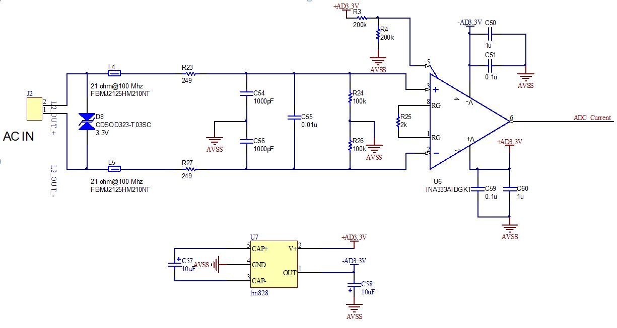
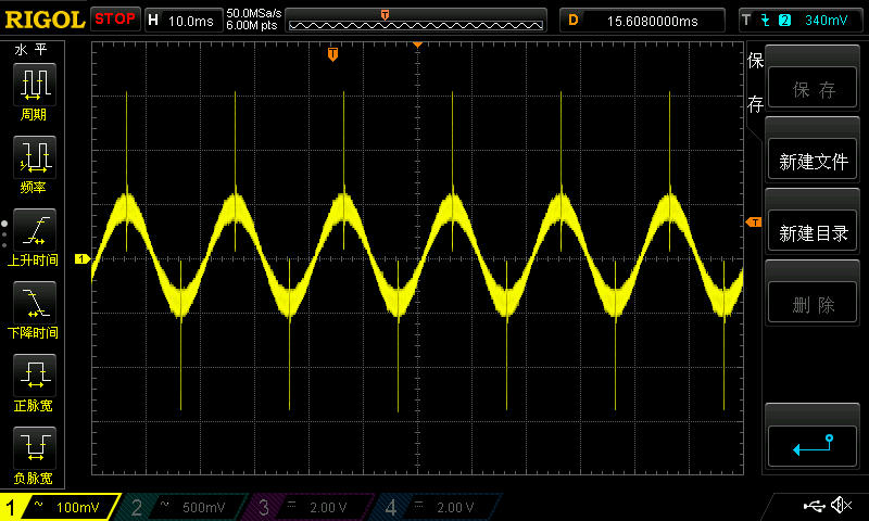
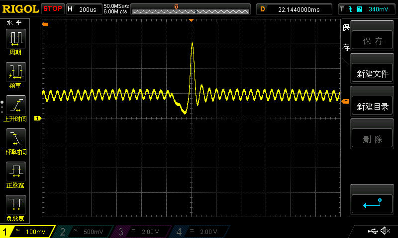
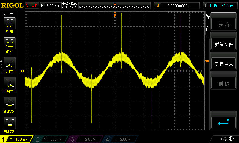
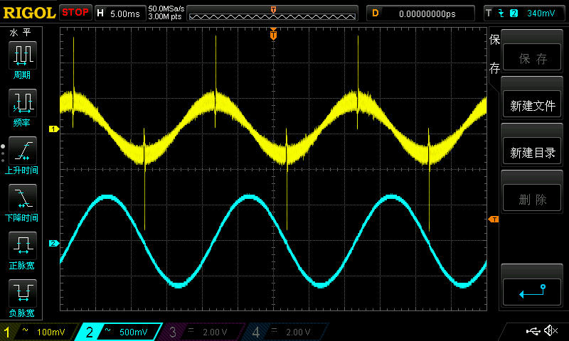
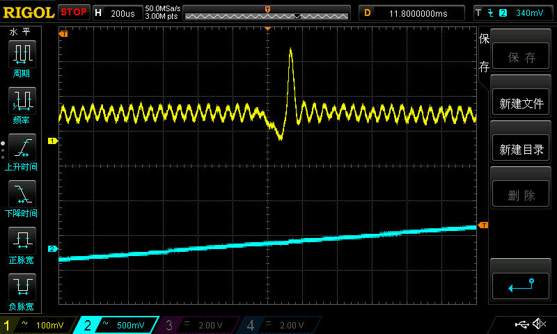
    I use an ina333  to amplify the signal from a Rogowski coil. At the ina333 output (netlabel ADC_CURRENT), I got the waveform 1. There are huge periodic spikes on the peak of the wave.  The detail is in the waveform 2.
    This circuit is identical to the Ti design TIDA-01063. I just change the opamp and power converter for low power reasons.
    My test board is an empty PCB. Only the components in the schematic are soldered. So, there is no other noise source on the board. I used both a 3.6v battery and lab DC power supply as a power source, and the result is the same.
    Why there is a spike? How can I remove it? 
    Thank you.
  • Not sure about that spike, but your Ref input needs to be lower impedance if you are trying to set up at 3.3V/2. It has a nominal 150kohm internal but you have added another 100k thevinin equivalent externally. You might try changing those to 2kohm temporarily and see if that is related to your spike. Also, it looks like you are doing a +/-3.3V supply? getting kind of close to the 7V abs max. 

  • Hi ,

    As Michael point it out, your pin 5 needs to low impedance source, see the attached image. You may connect the Pin5 to ground directly since you are using dual supply rails. Please let us know the findings after you made the changes. 

    Best,

    Raymond

  • Thank you, Michael. Thank you, Raymond.
    I neglected that I have changed the vref input.  This circuit is a little different from the TIDA-01063. That really increased the impedance.
    However, I directly connect the pin 5 of ina333 to the ground, and the result is the same.
    To avoid my first test board may be damaged, I made a whole new test board.
    The second board connects the ina333 pin 5 to the ground.  The waveform (wave 3) got at ina333 output is almost identical to the previous one. There are many spikes still at the peak.

    I use a +/-3.3V supply just for a better signal near zero. In my application, the input signal swing between 0~2.048v. 

    Maybe some problem in the filter circuit?In fact, that is the TIDA-01063 original design.

    I suspect the input signal which comes from a Rogowski coil may be wrong. But when I use another circuit ( two cascaded opamps) to amplify the same signal, the output wave is smooth, and there is no spike.

    I can't figure out what happened. Please help.

  • Hi,

    can you show a scope plot of the current signal which is to be measured by the Rogowski coil?

    Keep in mind that the signal of Rogowski coil is an induced voltage which is proportional to the change rate of current signal to be measured. So, very fast changes of the current to be measured will generate huge voltage spikes.

    Kai

  • Thank you, kai.

    I think the primary current signal which is measured by the Rogowski coil is correct.

    The blue curve in the first picture is the primary current. I use a current clamp to get this signal.

    The detail about the spike is also provided in the following picture. When spiking happens, there is no fault on the primary current.

  • I would recommend scoping your power supply line. That ripple seems odd and roughly calculates to 17kHz, while the LM828 is specified for around 12 kHz. Nonetheless your charge pump power supply should be scoped to be sure it is not the cause of the problem.

  • Hi ,

    Your current measurement seems to be smooth in sinusoidal, therefore, the voltage spike is likely not caused by Ldi/dt from the coil. 

    Inject a small sinusoidal  differential  signal at AC in (gain is 51) and please make sure your INA333 Op Amp stage is working properly. Connect 10kHz load to the output of INA333 without ADC connection, when you are verifying the operation of INA333 stage. 

    By the way, was ADC was operational when the above measurement is made? What type of ADC are you using? 

    My guess is that the voltage spike may have something to do with your AC frequency of input power, which is 50Hz. The spike voltage repeats at a rate of approx.100Hz.  How well do you filter out your AC input power frequency? I would follow Gerald's suggestion. I will definitely check out the DC output characteristics from your DC regulators. 

    In addition, Rogowski Coi has very high BW up to 20MHz. Your low pass filter from R23 and C54 has BW at 1/(2*pi*R23*C54)=639kHz. You may consider to shift the pole further to the left, and reduce your LPF's bandwidth. Also, please reduce the BW of the measurement scope to 20MHz or so. 

    Can you tell us what was your current measurement application? 

    Best,

    Raymond

  • Hi,

    make no mistake: Your sine wave isn't smooth but has steep edges! Remember, the Rogowski coil is "calculating" the mathematical derivative of current. So, what counts is not big pulses of the current, but big change rates of current. You can have big change rates without having big pulses. And that's exactly what the scope plot shows:

    Of course, the scope is adding lots of noise to the blue curve and maybe the current clamp doesn't have high enough bandwidth to show the edges much clearer. But the points of big change rates are there and are properly detected by the Rogowski coil.

    Kai

  • Thank you, Raymond. Thank you, Kai. 

    I think Kai is right. After I thoroughly check my test environment, there is another coil on the primary line. When I put the probe at the output of the second coil, I got this waveform. I think for some reason the second coil saturated, and this saturated coil made the primary current distorted. Although the distortion is very small, it really exists. So, the spike at the ina333 output is from the di/dt of the distortion.

    The blue curve is the output of the second coil.

    If the second coil can be removed, I believe the spike will disappear. But in my environment, that coil is permanent equipment.

    I think maybe I can smooth ina333 output waveform by post integrate circuit.

    Hello Raymond. I have changed the filter parameter., R23 and R27 are 5k, and C54 and C56 are 10nF. The output waveform became more clear.  But the spikes are still there. As we now know, the spike is from the primary current distortion, so it can't be removed by the filter.

  • Hi ,

    Thanks for Kai's support and expertise in finding the root causes. 

    About the LPFs, if you want to be more aggressive, you may put two 2-pole RC filter in series to have better high frequencies rejection, which LPFs will roll off at a rate of -40dB/dec rather than -20dB/dec. However, it won't help you with the spikes, since it is low frequency.

    I think that you are measuring AC power line input current (~50Hz), otherwise you may use high pass filer to get rid of the noise. In any case, you need to fix the distortion first at the input coil. 

    I am going to close this inquiry. If you still have questions, you may continue to post on this thread or open a new one. 

    Best,

    Raymond

  • Hi,

    keep in mind that an integrator must follow the INA333. So, you should be careful with all too much low pass filtering in front of the integrator. The output signal must look a bit "noisy". Keep in mind that it is no real signal but the mathematical derivative of current signal. Only after the integration it becomes a meaningful signal.

    Kai