A related question is a question created from another question. When the related question is created, it will be automatically linked to the original question.
If you have a related question, please click the "Ask a related question" button in the top right corner. The newly created question will be automatically linked to this question.
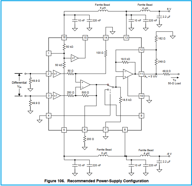
"Operate the two positive supply pins and the two negative supply pins at the same voltage. Using separate sources on the two pins risks forward-biasing the on-chip parallel diodes connecting the two supply inputs together. +VCC1 (pin 13) and +VCC2 (pin 16) have two parallel diodes that are normally off if the voltage at the two pins are equal. The same is true for –VCC1 (pin 8) and –VCC2 (pin 5)."
And:
"The recommended external supply configuration brings ±VCC into the output stage first, then back to the input stage connections through a π-filter comprised of ferrite beads and added decoupling capacitors at +VCC2 (pin 16) and –VCC2 (pin 5). Figure 106 shows an example decoupling configuration."
Incidentally, the separate supply connections for the output stage and input stage simulated to show incrementally improved HD performance vs using only one supply pin - that showed up in the full package model simulations.
Those Ferrite beads are not really 4uH inductors as shown, but lossy inductive elements, you might look at the EVM BOM to get a part number.
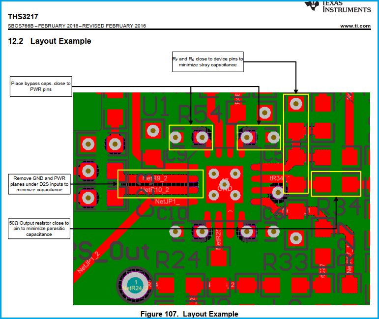
The EVM shows a much better layout compared to the "layout example" of datasheet. The "layout example" of datasheet has vias in the solder pads which I do not like at all due to soldering problems:
The EVM layout, on the other hand, does not have this: