This thread has been locked.

If you have a related question, please click the "Ask a related question" button in the top right corner. The newly created question will be automatically linked to this question.

AMC1301: Floating inputs fault

Part Number: AMC1301
Other Parts Discussed in Thread: AMC1300

Hi, I'm a newbie at using this forum to ask questions, so I hope I can express my problem well, and that you can help me.
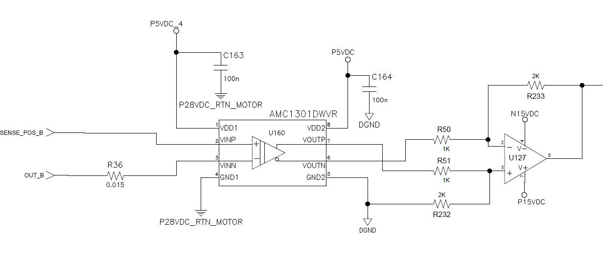
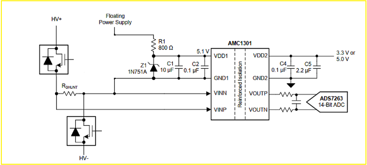
I am using in a design the amplifier AMC1301 to measure the current that circulates through each of the phases of a motor, in the drawing below I represent the architecture of each of the phases approximately.
My problem is that we can observe that without current circulating, and with a voltage at the input of 0V, the output goes to 2V. I have identified it as a floating input problem, but putting a pulldown resistor has not fixed it. Can there be another cause that we have not identified? Is it not correct to use a pulldown resistor or is there a better architecture?

Thank you very much and best regards.


  • Hi,

    When you say the output goes to 2V, do you mean differentially? Can scope shots be provided?

    What is the size of your shunt resistor? Can you provide a schematic? 

    Is your high side GND connected to the negative input? 

  • Hi Alexander, thank you for answering.

    Yes! The 2V output is measured dfferentially. I can't provide scope shots, but I'll try it.

    Our shunt resistor value is 0.015 Ohm, and we have the bias current limiter resistor too, as you could see at the schematic (shunt resistor is in another page):

    The high side GND is connected to the return reference ground, the same as the ground reference from the input.

    We have detected one problem which could be the common mode voltage input, which is greater than the maximum rating. So we are testing now an architecture as the below:

  • Hi,

    I wouldn't do that because the mismatch of external resistors (manufacturing tolerances, mismatch of temperature drifts and long term drifts) can heavily erode the common mode rejection of AMC1301. Instead, I would do it as recommended in section 11 of datasheet.

    Kai

  • Hi,

    I understand the resistor mismatch problem, but I think we could look for some good characteristics resistors in this case.

    I do not understand how the section 11 schematic could help us, the power supply of both sides of the amplifier is supplied by isolated converters, dedicated, and with the same ground reference. Furthermore, our shunt resistor is not connected directly to ground, because it is measuring between driver transistors.I think it's not the same application.

    Thank you!

  • Hi,

    Can you provide the schematic showing how the high side GND is connected to the same GND for the shunt? 

    I suggest fly-wiring a GND connection such that it is similar to figure 52. and 54. in the datasheet to see if it fixes the common-mode issue. 

  • Hi Alexander,

    this is the last schematic in which we are working. Our Voutput is still saturated, and I am thinking about the common mode voltage maximum rating, which is VCC+0.5V.

    Are we having 28V as common mode voltage in the positive input terminal? We couldn't capture with the oscilloscope, but some of the amplifiers are damaged, and they are always saturated. Could it be this the cause? We have some alternative using the AMC1301 or we have to change to another one?

    Thank you very much for your help.

  • Hi,

    I have modified figure 54 of datasheet a bit:

    Remove voltages "P5VDC_4" and "P28VDC_RTN_MOTOR" from the high side of AMC1301. Take an isolated supply voltage from a SELV or an isolated DC/DC switcher and power the hide side with it, as implied by the picture above. Make a connection between "GND1" and "VINN" of AMC1301 and connect your shunt to the high side of AMC1301 as shown in the picture.

    Kai

  • Hi,

    Yes, it does appear that you have 28V common-mode to the inputs of the device which would explain the damage you are seeing. 

    As Kai mentioned, you should use a floating power supply and connect the negative input to GND1. With the negative input connected to GND1, the device floats with the measurement, keeping the common-mode range within the supplies of the device. 

    I do not see an issue with using the AMC1301 for this application unless you plan on performing EMI testing, in which case I would recommend switching to the AMC1300. 

    Thank you for your help here Kai!  

  • Hi Alex, Kai

    thank you very much for your answers!

    We have tried this architecture but we are seeing saturated outputs anyway. We have connected another isolated supply reference to GND1 following Kai's modified schematic, and we see Vin=0mV approximately. This input is fixed, and the output is always saturated.

    I think we probably have solved the common mode problem, but now we are really facing the floating input problem, because if our driver is connected like the schematic I attached before, the shunt resistor is between two gates, so if the gates are opened, the input voltage measured could be floating.

    Could be this our problem? Are there solution, something like a pulldown resistor? Or it's better to change the IC and look for another solution?

    Thank you so much in advance.


  • Hi,

    when you have connected "VINN" to "GND1" at the AMC1301 there should no longer be an issue with the input bias currents because they do no longer float then.

    Can you show how you manage the different commons (signal grounds, power grounds) in your circuit and protective earth? Maybe you have an unwanted floating between the high side and low side of AMC1301.

    Kai

  • Hi Kai,

     I think we have found the issue, and it's what you have pointed. The reference of the driver supply is the motor reference, so we can't use a floating supply for the AMC1301.We have tried to change that, but it's not possible in our full design.

    We have thought about adding an aditional previous opamp with better common mode rejection, in order to solve the 28VDC common mode problem. I think that's our main problem here and we can't solve it changing VINN/GND1 reference :( Thank you anyway, you have helped us a lot.

  • Hi,

    I'm happy to hear that you found the source of the issue. If there's anything else we can help with, please let me know or feel free to post on E2E again.

    Thank you for your support as always Kai!