This thread has been locked.

If you have a related question, please click the "Ask a related question" button in the top right corner. The newly created question will be automatically linked to this question.

LMV321: low-pass filter

Part Number: LMV321
Other Parts Discussed in Thread: , TINA-TI

Hi Team,

I want to use lmv321 to design a low-pass filter below 20kHz, mainly filtering the frequency of about 15MHz.

  1. Is there a recommended reference design?
  2. When designing filters with operational amplifiers, are there any precautions in the design of peripheral circuits?

Best regards 

Wesley Huang

  • Hi Wesley, 

    Did you mean to say 15kHz?

    Please refer to the following cookbook circuit: http://www.ti.com/lit/an/sboa293/sboa293.pdf.

    Let us know if you've any questions. 

    Regards,

    Bala Ravi

  • Hi Bala,

    Thanks for your reply

    1. I want to use lmv321 to design a low-pass filter below 20kHz, mainly filtering the noise  whose frequency is about 15MHz.

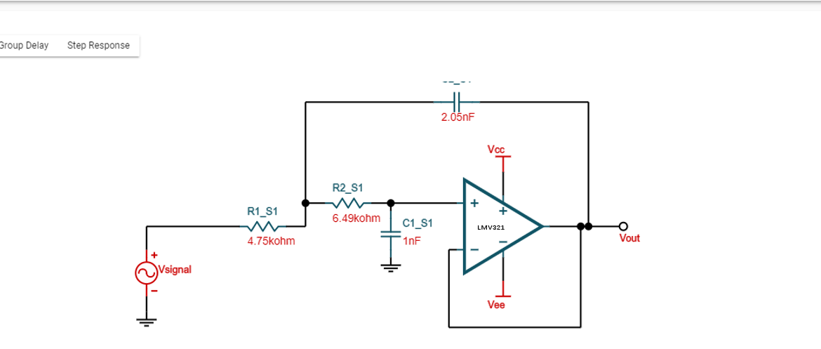
    2. here is the circuit from the webench filter designer, could i use it for my purpose? could you please double check with this schemaic?

    Best regards 

    Wesley Huang

  • Hi Wesley, 

    No problem! First, I would highly recommend using LMV321A for your application. LMV321A is the improved version of LMV321.

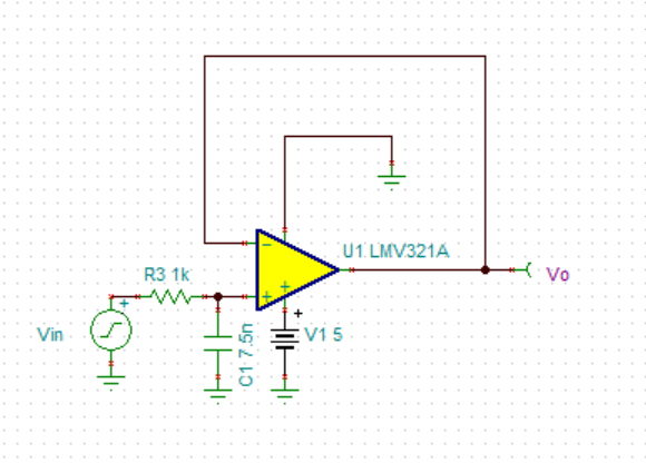
    Next, the circuit above will work fine. But, you can reduce the number of components used if you go with the below circuit:

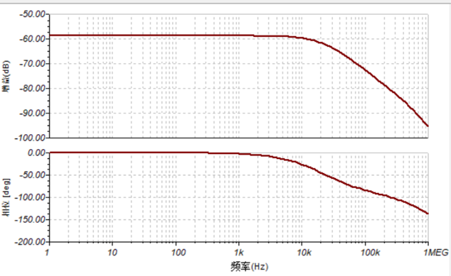
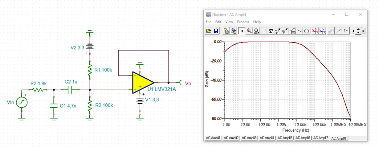
    AC Response: 

    You can simulate this circuit using TINA-TI. I've also included the file here: LPF_LMV321A.TSC

    Let us know if you've any other questions. 

    Regards,

    Bala Ravi

  • Hi Bala,

    Thanks for your reply.

    the system just has the 3.3V and 5V VDD, and after i adapt it to 5V in TINA, i found that the AC Response has changed. could you please provide reference design via the 5V or 3.3V VDD and 2 stage filter?

    Best regards 

    Wesley Huang

  • Hi Wesley,

    when modifying a circuit powered by a bipolar supply voltage into a circuit powered with a single supply voltage, you need to introduce a "pseudo ground", best at midsupply.

    Can you show a schematic of your present circuit?

    Kai

  • Hi Bala,

    Thanks for your reply.

    Here is schematic and AC analysis.

    Could you please provide reference design via the 5V or 3.3V VDD and 2 stage filter?

    Best regards 

    Wesley Huang

  • Hi Wesley,

    please tell more about your application. What is the environment of this circuit? Do you plan to build more than this low pass filter? What have you designed so far?

    Kai

  • Hi Bala,

    Thanks for your reply.

    1. This circuit is used to filter the signal from the NFC in the U-KEY which is used for Financial security

    2. I haven't design the filter right now, and i want to try both the 1 and 2 order filter circuit to see which one is better.Could you please provide the 2 order reference design with LMV321A? 

    3. Why does VDD change the AC response?

    Best regards 

    Wesley Huang

  • Hi Wesley,

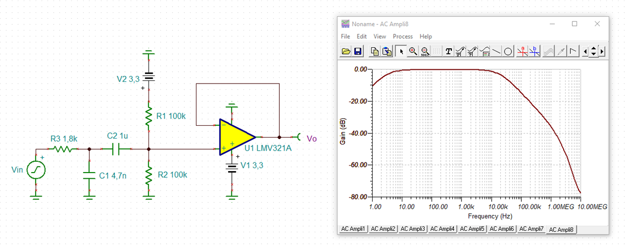
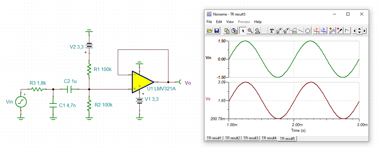
    I think a passive 1st order low pass filter, as recommended by Bala, is sufficient. This one here uses an auxiliary ground at midsupply to allow a signal swing to both polarities:

    1513.wesley_lmv321a.TSC

    Kai

  • Hi Bala,kai

    Thanks for your reply. I appreciate that so much.

    I cannot find any document in TI.COM or internet about how to design the 2 order low pass filter, could you please share any document or note about how to design the design as you posted above?

    Best regards 

    Wesley Huang

  • Hi Wesley,

    much can be found in the datasheets of OPAmp. Many of them contain usful information on how to build such a filter.

    Here is a nice appnote:

    Or have a look at this TI's Filterdesign-tool:

    Kai

  • Hi Team,

    Thanks for your sharing.

    1. Unfortunately,I can‘t visit google because of the chinese policy. Could you please share the picture to me?

    2. From the 2 order filter circuit you provided, the C2 and R2 is worked as LPF. Why there is a LPF in the 2 order low pass filter?  if not, what's the function of the C2 and R2 in this circuit?

    Best regards 

    Wesley Huang

  • Hi Wesley,

    here's the appnote as PDF document:

    sloa049b.pdf

    The circuit I recommended to you contains a first order low pass filter (R3, C1), because I thought that such a low pass filter would be enough to suppress 15MHz.

    R1 and R2 generate a pseudo ground at midsupply. Please see that transient analysis. A pseudo ground is important, because the output of an OPAmp powered with a single supply voltage cannot go negative. So, every negative half wave would be lost.

    And C2 is needed to separate the two different DC potentials. It provides an AC coupling but blocks the DC potentials.

    C2, R1 and R2 form a first order high pass filter. You can see this in the frequency analysis.

    Kai