This thread has been locked.

If you have a related question, please click the "Ask a related question" button in the top right corner. The newly created question will be automatically linked to this question.

TL026: Is the TL026 suited for my AM infrared signal?

Part Number: TL026
Other Parts Discussed in Thread: TL082

Hello,

I am currently working on a infrared receiver and the problem is that the amplitude of the received AC Signal is changing in correspondence to the distance between the transmitter and receiver.

The received ac signal has a frequency of 40kHZ and the Peak-to-Peak Voltage ranges from 10mV to 40mV according to the distance. I have a supply voltage of +/-3.3V.

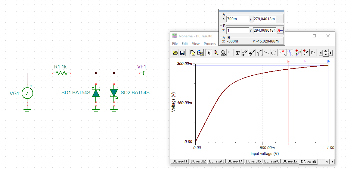
Is the TL026 capable of providing a constant Output Voltage of 700mV to 1000mV with the given AC Signal in spite of the changing distance issue? 

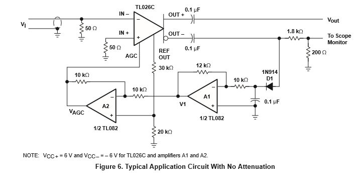
Will the Circuit with no Attentuation (Fig.6) which is given in the datasheet work in my case?

Thanks

Dmitrij

  • Hello Dmitrij

    Welcome to the e2e forum.  The TL026 AGC circuit will make a more constant signal level. AGC does have a response time so the very first pulse may be bigger as the AGC tries to adapt. What is the intelligence (purpose/data stream) in the IR signal?  It should work provided there is a preamp placed between the IR diode and the relatively low input resistance of the TL026.

  • Hi Dmitrij,

    if your signal is a square wave, a simple diode limiter could do the trick:

    dmitrij_tl026.TSC

    Kai

  • This is my current circuit follwed by a bandpass filter.

    C2 and R3 decouple the AC singal from the DC Voltage which is genereated from the ambient light. The  signal after the non-inverting amplifier provides a Signal which varies between 3V to 200mV (Peak-Peak). My idea was to replace the non-inverting amplifier with the TL026.

    The IR Signal after the bandpass looks like this

  • Hi Dmitrij,

    have you thought about using a TIA (transimpedance amplifier)?

    Kai

  • The problem is that when I use a TIA the DC current from the ambient light will cause the OP AMP to saturate, thus losing my AC signal. I can reduce the amplification of the TIA so that the OP AMP won't saturate and place a HP filter afterwards. I found an "easier" solution using the Resistor R2, the HP filter.

    However my major problem is the  variation of the AC Signal due to  the chagning distance.

  • I built the circuit which is given in the Datasheet.

    I connected the AC Signal (200mV Peak-Peak, 40kHz) to the IN- PIN but I did not measure any voltage  at the OUT- pin. 

    Did I connect my output to the wrong pin and at which pin will I receive my ampflified Signal?

  • Hi Dmitrij,

    have you thought about using a comparator with a threshold voltage of 200mV?

    Kai

  • Dmitrij,

    Thanks for the waveform. That is a pulsed keyed modulation. Basically on/off (1 bit) modulation. The information is in the key state not the amplitude. AGC is not needed for that. Clipping is not a problem other than overload recovery time. 

    For the TL026 running at +/-3.3V, you can't use TL082 as the supply and common mode range headroom is not compatible. Replace TL082 with any >7V rail to rail input and output op amp.