This thread has been locked.

If you have a related question, please click the "Ask a related question" button in the top right corner. The newly created question will be automatically linked to this question.

INA220 / INA220-Q1: Measuring current of PWM-driven load

Part Number: INA220
Other Parts Discussed in Thread: , DRV103, INA230

Hello,

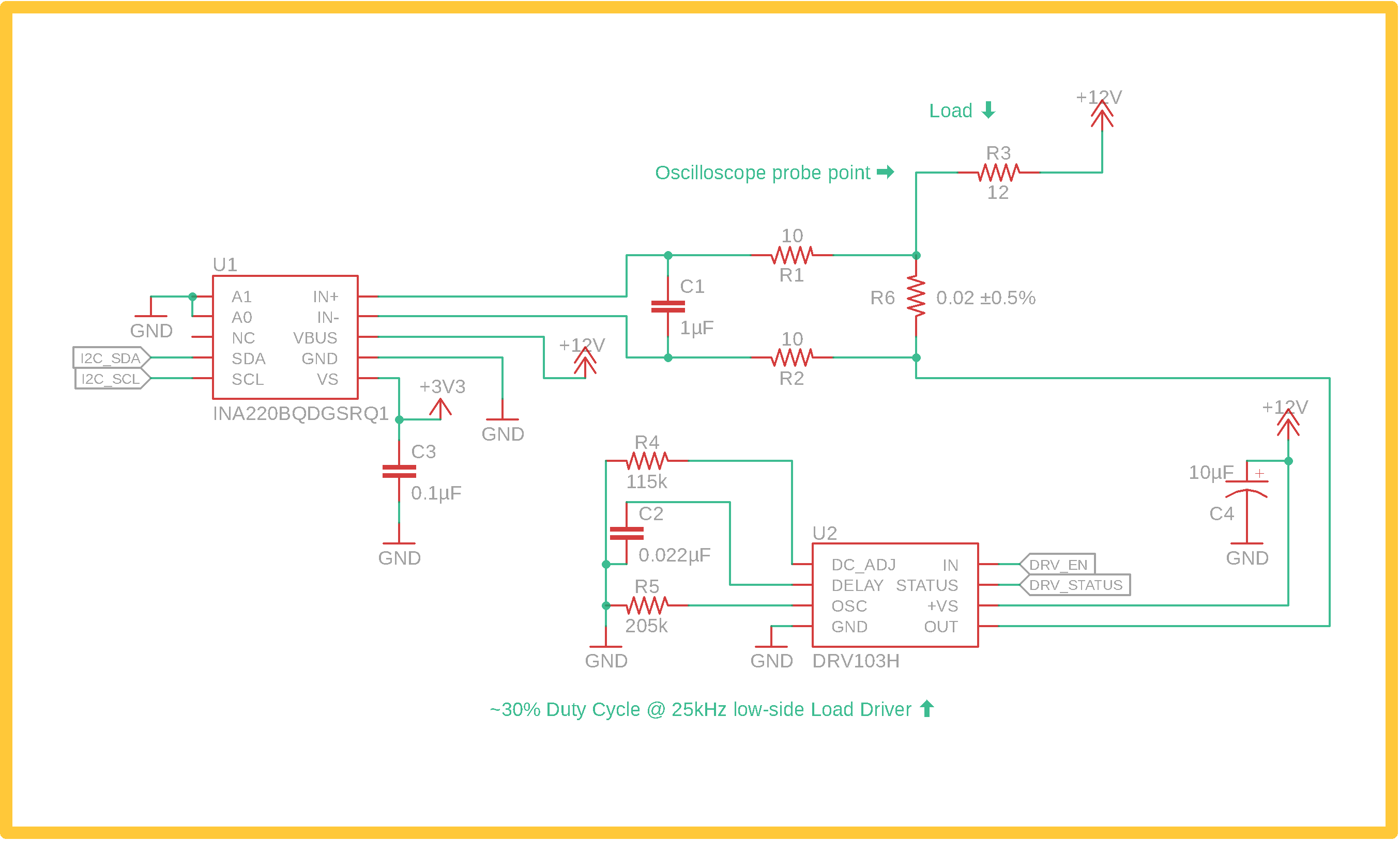
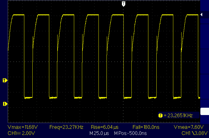
I'm using an INA220-Q1 to measure several types of loads. Some are resistive with a 100% duty cycle, others are resistive with a high duty cycle ~75%, and others are inductive with a low duty cycle ~30%.

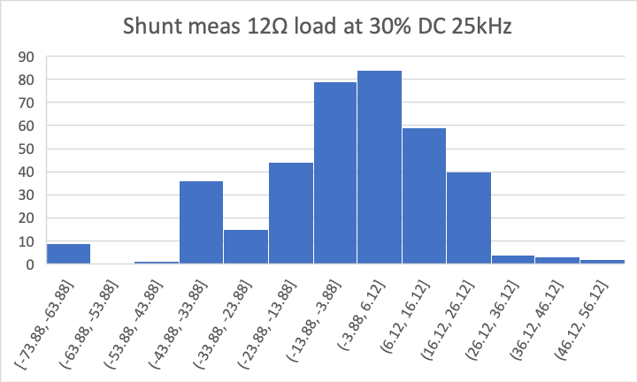
My INA220-Q1 setup is having trouble measuring the loads that are not driven at 100% duty cycle. I am using the 32-sample averaging mode for the ADC. The measured values for the high duty cycle load are fairly accurate although they do tend to jump about by about 100mA (on a ~1A load), likely due to the limited input filtering of the 5kHz pwm signal. My biggest problem actually lies with the low duty cycle inductive load. The INA always returns large negative current values for this load, even though I have clamping diodes that clamp the inductive effects.

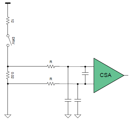
I am using the reference design given in the datasheet with 10Ω series resistors on the shunt measurement lines and a 1µF capacitor between those 2 lines. This sets up a sort of low-pass filter. Although I'd like to just raise the resistor values to lower the cutoff frequency of the filter, the datasheet specifies that the INA220's IN+ and IN- bias current is 20µA, which severely limits how high these resistors can be. As a test, I tried increasing my PWM frequency to 100kHz which I expected to put a positive voltage of about ~6-10mV across IN+/IN-, but it's still measuring -1 to -1.3A instead of about 0.4A. As a test, I also tried placing a resistive load into this circuit instead of inductive, and it returns smaller but still negative numbers (-500mA or so, when I would expect closer to +300mA).

Are there fundamental limits to how the INA220-Q1 can measure PWM current? I will continue testing and trying new changes, such as increasing the capacitor value in the filter, but at this point I'd appreciate feedback on whether I'm headed down a useless or worthwhile path with this chip.

Thanks

  • Hi,

    It appears you’re trying to measure the average of the “PWM current”. Theoretically it is doable as long as the averaging period is much greater than the PWM period. However, if the input common mode voltage is also PWM, it likely will cause problems. The device common mode is expected to be stable.

    To understand the problem better, please post relevant schematic.

    What will also help is to post differential input voltage (or load current being monitored) and common mode input voltage waveforms. Hand drawings are fine as long as they are properly labeled.

    Regards, Guang

  • Hi Guang, thanks for the quick response.

    VBUS is connected to the 12V rail, but you got me thinking about whether it is stable enough. As this is the same rail used to power the load, noise from the PWM switching is slightly coupled into the VBUS input. Could this explain some of the variability we've been seeing in the bus voltage measurements? Could it also affect the shunt measurements somehow? Would it be advisable to add a bypass capacitor or something to the VBUS input to help with this? I did not see any references to bypass capacitors or filters for the VBUS input in the datasheet.

    Attached is a schematic of the setup. In my original post I noted that this was an inductive load, but I am seeing the same results with a resistive load. I tested the same load with the same driver configuration on a circuit with and without flyback diode protection and saw the same results, so my schematic shows the simplest circuit that exhibits the measurement problem.

    Unfortunately I haven't been able to get useful shunt voltage measurements with the probes I have on hand. I do have a measurement taken at the low side of the load showing the PWM (low voltage means active, high means inactive), see below:

    Here are some histograms showing the low variance of data at 100% Duty Cycle (DC) compared with other driver configurations (same 12Ω load each time). Even at 80% DC, the measurements are fairly noisy. At 30% DC the numbers are often negative so not really useful at all. The units on the horizontal axis are mA.

  • Here's some more info. I've tried using the 32-sample averaging mode as well as 128-sample averaging for both bus voltage and shunt voltage conversions.

    I redid the histograms with common ranges so they can be more easily compared with each other, see below. I also graphed the bus voltage measurements to show how they become problematic when we use PWM to drive the load. At 80% DC 5kHz there is a lot of variability but they are somewhat close to the correct values. At 30% DC 25kHz the VBUS measurement is still in the ballpark of the correct value but the shunt measurement is very wrong. In the below graphs, current is shown in mA and voltage is shown in V. The left column shows current and voltage measured by the INA220 during my 30% DC tests, and so on.

    I've played around with a few changes to the shunt low-pass filter, including switching the 10Ω with 100Ω resistors, and separately swapping the 1µF with 10µF, but it hasn't seemed to help.

    Could you clarify how the INA220 ADC works w.r.t. non-DC signals? The 12-bit conversion time is 532µs but the sampling rate is 500kHz (2µs). I understand this to mean the signal is "oversampled" but over that 532µs how does it internally come to a conclusion on the voltage? At a PWM frequency of 5kHz, there are about 2.6 PWM periods for every 532µs conversion. Does the fact that the signal is changing so often cause the conversion data to be bad? If we use a PWM frequency of 25kHz, now there are about 13 PWM periods for each 532µs conversion. I feel like there could be a problem here but I don't understand enough about the delta-sigma ADC process to be sure.

    One idea I had was to slow the heater driver PWM down to <1kHz to take advantage of the Nyquist Sampling Theory. The lower limit of the DRV103 is 500Hz which would be very close to the maximum necessary to meet the Nyquist sampling requirements. This wouldn't work well for the inductive loads though since they operate better with a higher frequency. Does the INA220 require the maximum frequency in the current signal to be <= 1/2 the conversion time in order to measure correctly? Or should the delta-sigma ADC front-end be able to accurately measure the average amplitude of higher frequencies?

    Related to this, how should I read the frequency response given in the INA220 datasheet (see below)? It seems like there's large signal loss for frequencies higher than 1kHz, so is this device just unable to measure the average voltage amplitude of a 5kHz or 25kHz PWM signal?

    Thanks!

  • Hi Nathan,

    Thank you for the detailed background information.

    If you’re to measure instantaneous values of the circuit, then yes, the INA230 is not fast enough for 25KHz switching frequency. Since you’re interested in DC value, it is less of a problem.

    The biggest issue is the PWM common mode voltage, as your scope shot shows. This is the main cause of poor repeatability shown by the histograms.

    There might be a solution if key components are slightly rearranged as shown in this diagram.

    Regards, Guang

  • Guang, thanks for pointing that out - I can see how that would be a problem!

    We're now looking into the possibility of placing the shunt either below the DRV103 or above the load such that the shunt doesn't see large common mode voltage changes every PWM cycle.

    Could it be said that my design ran into the limits of the INA's "common mode rejection ratio"? I see that the INA220 has a common mode rejection of 100-120dB although the frequency range isn't given in the datasheet.

    I see the 2 additional capacitors you added to the differential lines. Do you have any recommended values for those capacitors or any resources where I can learn more about their purpose?

    Edit: One other thing.. does this explain the poor repeatability of VBUS measurements? VBUS is connected to the 12V rail so is always nominally at 12V, although it sees a small amount of noise coupled with the PWM switching.

    Thank you!

  • Hi Nathan,

    You can look into this post for information about the common mode filters.

    The problem does not entirely fall under the realm of CMRR. The CMR spec in the data sheet is at DC and doesn’t apply when fast PWM transitions are present.

    Either of the topologies you’re considering should give more consistent readings.

    Regards, Guang