


Other Parts Discussed in Thread: THS4631
So this input capacitance issue is coming in from a number of directions lately - let me attempt a survey of where there might be some confusion,
1. So those of us (like Bruce Trump and myself) that have been introducing op amps since the mid 1980's treated the input capacitance as two separate but equal common mode caps on each input to ground with a differential C between the two inputs.
2. One of the most obvious ways this gets into the frequency response is a simple non-inverting unity gain buffer with a higher source R into the V+ input. The signal will get a pole from that R and the V+ node Ccm value. the Cdiff and the Ccm on the inverting input are not seen by the signal up to the V+ node as adding to just the Ccm on the V+ input. Up through the LG rolloff, the V-pin is moving in phase with the V+ pin bootrapping out the Cdiff term. The inverting Ccm capacitance does appear part of the load on the output interacting with the open loop output impedance in the overall loop gain - this is why on the higher speed VFA parts at unity gain, a 20ohm feedback R is sometimes seen.
3. Apparently, there are at least a couple of sources that treat the input common mode cap as the sum of the two capacitors and then splitting that between the two inputs.
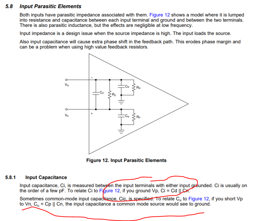
a. This old 1998 spec review by Jim Karki at TI Dallas SLOA011 updated in 2018 as the A version. Don't know if any changes were made, but it might be prudent to have scanned and updated where needed - this document shows this - the schematic is correct his comments are odd - the first line with Vp ground should just be Cd+Cn which is how you parallel caps - his equation is for series caps. The 2nd comment should be Cp + Cn testing both in parallell, probably open loop - not a physical test but only a sim test. So that Cp probably should be the cap on the positive node, figure not labelled right.
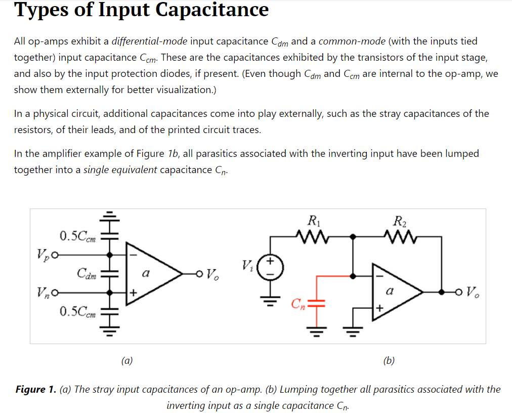
3b. And then in 2019 Dr. Sergio Franco published this,
Where this figure appears - the text again suggests the input common mode capacitance can be derived driving the two inputs together - must be open loop. If you make a single measurement for both caps, you could imagine why you would place 1/2 that measured value on each input as he does. Bit of a nomenclature disconnect, Bruce and I (and ADI) would prefer to call each common mode cap as a Ccm.
So his text is implying tying the inputs together to get this cap - I was asked about this and here is that test for the OPA350. I was using the OPA350 to show how messed up a lot of the models are in this article - but then I tested the most recent update to the model and its measured input C matches the data sheet specs if you interpret the Ccm as appearing on each input and Cdiff between them.,
5008.Input Impedance Extraction and Application for High Speed Amplifiers May29.pdf
here was a test of tying the two inputs together to get the combined 2*Ccm test again using the high LC tricks.matches data sheet perfectly if the datasheet means the Ccm is on each side,

4. I looked a little to see how to interpret the ADI numbers, did find this app note where it implies their Ccm is supposed to be on each input with a seperate Cdiff - the app note is about how to measure Cdiff - looks like doing a transimpedance test to extract, something I have tried as well -
So yes, if you do not know for sure that an older part like the THS4631 that the specified Ccm is actually the sum of the two Ccm on each input, you would be in some trouble - the 1st check would be to see what is in the simulation model and hope it is accurate - that is very suspect also as the THS4631 model does not have any Cdiff (nor is there any number in the datasheet).
The comment that Karki's app note tells you how to interpret this only applies to pre 2001 TI parts and not to BurrBrown (OPA) parts. Not sure about the LMH or LM national parts.

