This thread has been locked.

If you have a related question, please click the "Ask a related question" button in the top right corner. The newly created question will be automatically linked to this question.

4-20mA current loop: measurement changes when earth GND connected

Part Number: INA219

Hi group,

I am following up on a previous post regarding the use of INA219 for a current loop measurement (question was resolved, with thanks to Ian Williams).

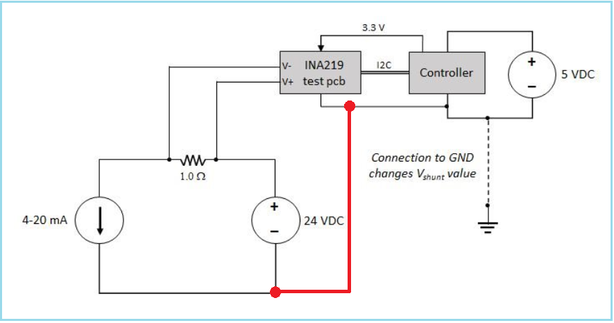
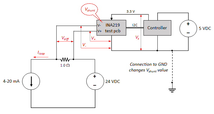
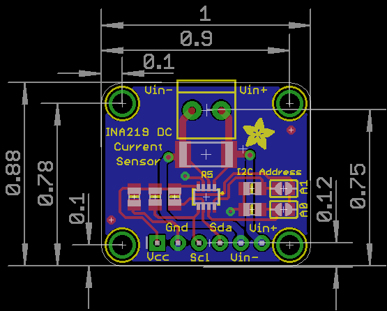
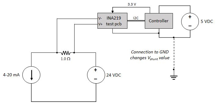
We have implemented the test circuit shown below, where the current loop and a controller are supplied by separate, isolated (floating) DC supplies.  The INA219 is on a breakout board (details at https://learn.adafruit.com/adafruit-ina219-current-sensor-breakout/downloads).  The controller provides 3.3V and is connected to SCL/SDA of the INA219 via the breakout board.

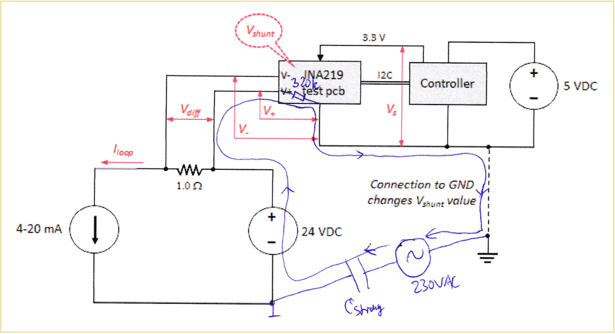
The expected V_shunt value is read back from the INA219, except if an earth ground is introduced on the 0V side of the +5VDC supply as shown.  In that case, the measured value drops by 10-20%.

We are trying to understand why the measurement would change.  Does this introduce another pathway for current flow, through the INA219?  Or is there another reason this would affect the measured V_shunt?  It seems we are making an assumption about isolation that is not valid.

Thank you in advance for any theories or suggestions.

  • Hi Kevin,

    The inputs of the INA219 do have some bias current (20uA typical), so there is a current pathway from the inputs to GND, it is not isolated. The 10-20% shift does seem extreme, though.

    If you use a multimeter and measure the VIN+, VIN-, VS, and GND pins, how do they change with the GND connected vs. disconnected?

    Best regards,

    Ian Williams
    Applications Manager
    Current Sensing

  • Hi Ian,

    During testing, we did measure from Vs to GND and VIN+ to GND (i.e., the GND reference of the INA219 breakout board).  We did not check VIN-, we can try that as well when making additional measurements.

    Here are the other values:

    Floating: Vs-GND=3.3V, (VIN+)-GND=0.85V

    Grounded: Vs-GND=3.3V, (VIN+)-GND=1.52V

    Since both supplies are isolated (floating) as shown, we were not quite sure what to expect between Vs and VIN+, but in the end the perceived "bus voltage" is quite small.

    Thank you for your thoughts on this.

    Best regards,

    Kevin

  • Hi Kevin,

    I think a signal ground connection is missing at the input side of INA219, as shown in figure 29 of datasheet, allowing the input bias currents of INA219 to flow back to signal ground:

    Kai

  • Hi Kai,

    Thanks for your message.  Your point is related to the original question, whether we can make this measurement while keeping the two supplies isolated from each other (i.e., not tying 0V of the two supplies together).

    It seems to work until the earth GND is introduced, which comes as a consequence of plugging external equipment to test connectors on the controller card, which then creates the path shown as a dashed line.  I'm not sure why that would affect the measured V_shunt value.

    Best regards,

    Kevin

  • Hi Kevin,

    can you please show an exact schematic of your test circuit? And please add the measurement values into this schematic.

    Kai

  • Hi Ian,

    Sorry for the long delay, we were setting up a second unit to make those additional measurements.  We measured the voltages and current externally as shown below, as well as reading back the reported shunt voltage from the INA219.

    Value No GND With GND
    Vs 3.30 V 3.30 V
    V+ 0.772 V 1.304 .. 1.319 V (*)
    V- 0.768 V 1.301 .. 1.314 V (*)
    Vdiff 4.0 mV 4.0 mV
    Vshunt 3.97 mV 3.66 mV
    Iloop 3.99 mA 3.99 mA

    (*) V+ and V- are fluctuating when GND is introduced

    So, the externally measured loop current and voltage across the shunt resistance remain consistent and as expected when an external ground connection is introduced.  However, V+ and V- become unstable; these are measured across the two supply "domains" (possibly the 0V reference in the 5V power domain is now noisy?).

    The shunt voltage reported by the INA219 also changes - would that be expected in this case?  Are there any other measurements you would suggest?

    Note that we use the maximum averaging period.  Are V+ and V- averaged separately before computing a difference, or is the difference (V+)-(V-) continually averaged?

    Thanks for your help,

    Kevin

  • Hi Kai,

    The schematic for the INA219 test board can be found at learn.adafruit.com/.../36267 (it is from Adafruit).

    Unfortunately I cannot provide a schematic for the controller unit, it is a 3rd party design.  I have added some measurements to the high-level block diagram in the previous post, maybe that can help to understand the issue?

    Thanks,

    Kevin

  • Hi Kevin,

    I think that this happens:

    Kai

  • Hello Kai,

    Thank you for that illustration.  It makes sense that there must be another path for current flow that is affecting the INA219 readout.

    It is still not clear to me why V_diff (measured externally) is different than V_shunt (reported by the INA219).  Wouldn't they be similarly affected?  Maybe it requires a full understanding of the internal operations of the INA219 and the DMM.

    Also, the offset when GND is connected is not fixed - at different I_loop values, the error changes proportionally.  For example with I_loop = 15 mA, V_diff = 15 mV but V_shunt = 13.68 mV.  At 10 mA, the values are 10 mV and 9.16 mV.  So, it appears V_shunt is always ~ 0.92 of the expected value.  Would you expect such a proportional response, rather than a fixed leakage?

    Thanks again for your ideas on this.  If you can think of other measurements that could be useful, please let me know.

    Best regards,

    Kevin

  • Hi Kevin,

    schematics in datasheets are always highly simplified. Sometimes it's difficult to find out what's really going on inside such a chip :-)

    I would run a test: Supply both circuits with batteries, without any connection to mains voltage. But have the signal ground of INA219 connected to safety ground. Do you still see an error?

    Then exchange one (later both) battery by a SELV supply. Look for a SELF supply which specifies the stray capacitance between mains voltage and output and choose a supply with very low stray capacitance.

    Kai

  • @Kai - thank you for the suggestions, those tests will give some meaningful insight.  It will take some time to set up and execute what you described.

    @Ian - is there anything internal to the INA219 that you can share, which might help to explain this behavior?

  • Hi Kevin,

    if you cannot make the connection as shown below

    have you thought about using an isolation amplifier?

    Kai

  • Kevin,

    There is nothing internal to the INA219 that would cause an 8 drop in measurement at the pins vs what is measured at the shunt. I read that this is a 3rd party board, is it possible to post a layout image to look at how the traces are handled between the shunt and the device?

  • Hi Carolus,

    The layout for the INA219 test board can be found in different resolutions here (it is from Adafruit).

    Here is a copy of what is posted there (licensed to Adafruit, all rights reserved):

    Thank you,

    Kevin

  • Kevin,

    Nothing about this layout stands out as a source of this error either. The shunt traces are small and Kelvin connected to the shunt, which should be optimal in terms of layout introduced errors. 

    The fact that the pins are continually fluctuating as you say when you introduce earth ground on the 5V supply side leads me to believe that this is most likely being caused by a reference issue, and I believe Kai is correct, you need to have some point in the circuit (either your connection or internal to the 24V supply) where this supply can also reference the same ground somewhere in the circuit. 

  • Hi,

    I think there's a misunderstanding. In order to make the adafruit board freely configurable, connections from the input lines to any potentials are avoided and only the shunt is connected. But this does not mean that the INA219 should have the input lines totally floating. I have never seen the INA219 with floating inputs in an industrial circuit.

    So I agree with Carolus and would introduce a connection as shown in this earlier post:

    Kai

  • Kai, Carolus,

    Thank you both for your responses and explanations.  It seems this relates back to the original question (linked here and at the top of the thread) of whether the INA219 can be used when its GND is not referenced to the voltage source in the measurement loop.  However, the original question did not include some of the further details discussed here.

    We will look into whether we can create that common 0V reference between the DC domains, although there are other design constraints which make that difficult.

    Note that, based on our tests, the results are correct and stable when both DC sources are truly "floating", i.e., neither is referenced to an earth GND.  From what you've said, though, that does not seem like a valid approach, so I suppose that behavior is not guaranteed.

    Thank you,

    Kevin

  • Hi Kevin,

    that it works at all, without the input bias currents making the INA219 go into saturation, which would be the case for most other current monitor chips, has to do with the built-in 320k resistance:

    This resistor provides a current path for input bias currents. But at the same time it makes issues when having one or more individual signal grounds connected to protection earth AND when the individual signal grounds are floating to each other. Then you will need a true and low ohmic potential equalization. So an equipotential bonding only via this 320k resistor cannot be recommended for industrial use. It might work in low EMI, low noise, fully isolated or fully battery powered applications, but not in standard industrial applications.

    Kai