Other Parts Discussed in Thread: OPA2355
Dear TI team,
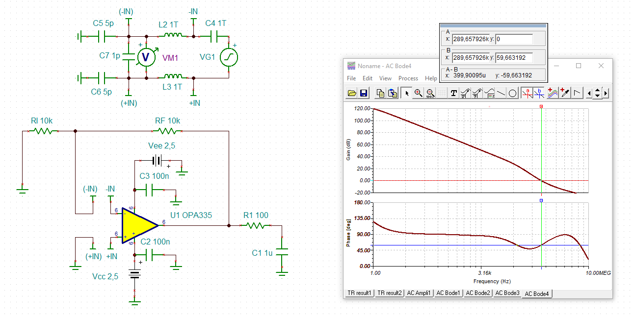
I would like to ask about Input impedance and capacitance connected to the output.
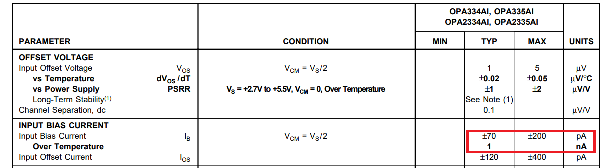
1. What is the impedance value of each input terminal (+ pin, ₋ pin) and its deviation?
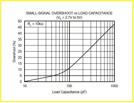
2. Is there a recommended value for the capacity connected to the OPA2335?
(How much capacity should be kept below, etc.)
Best Regards,
Y.Ottey