This thread has been locked.

If you have a related question, please click the "Ask a related question" button in the top right corner. The newly created question will be automatically linked to this question.

TLC272: TLC272 and OP2325 input/out impedance and power consumption

Part Number: TLC272
Other Parts Discussed in Thread: OPA2325

Hi there,

I am looking for the input/output impedance and power consumption of TLC272 and OP2325. 

Does anyone know what they are? I looked up the datasheet, but there was no mention about them at all.

If anyone knows these values, can you help me out?

Regards,

Arti

  • Former Member
    0 Former Member

    Hi Arti,

    Thanks for your question and welcome to the forum!

    So the two parts in question are actually supported by different teams.  If you don't mind, I'd recommend starting a second thread as well about the OPA2325.  That way the team that supports that part will work it out in parallel and give you advice more specific to that product.  By the way, I'm assuming you meant the "OPA2325" because the question mentions the OP2325, but that is not an existing part.  I'm guessing this is just a typo.  Please correct me if I am mistaken.

    On to your question.  I will address it for the TLC272 in 3 parts. 

    1.  Input Impedance - The input resistance is not typically specified because it is so large as to be irrelevant.  Instead, it is a good idea to consider the bias current of the device, which can be important if you have a large source resistance or any other large resistance connected to the input.  However, if you look at the left column of the first page of the datasheet, you will see the spec you're asking for (see below).

    2. Output Impedance - Usually this is included in the data sheet, but yes.  I could not find it either in this one.  I don't want to speculate too much, but this part dates back to 1987 and it's hard to say why the decision was made not to take the data at that time.  If it is a real issue, I can help you find a similar part.

    3.  The power consumption of the part is not intrinsic to the part.  You need to take into account the operating voltage and quiescent current, which can change a bit with temperature.  You also need to take into account the power that is dissipated by the current the amplifier provides.  These topics are covered in detail in this presentation.

    Please let me know if you need any further help.

    Regards,

    Daniel

  • Hi Daniel, 

    Thank you so much for your response. It is really helpful. 

    For the output impedance, I don't mind to have an approximate value. If you could help me out, it will be very appreciated.

    Regards,

    Arti

  • Hi Arti,

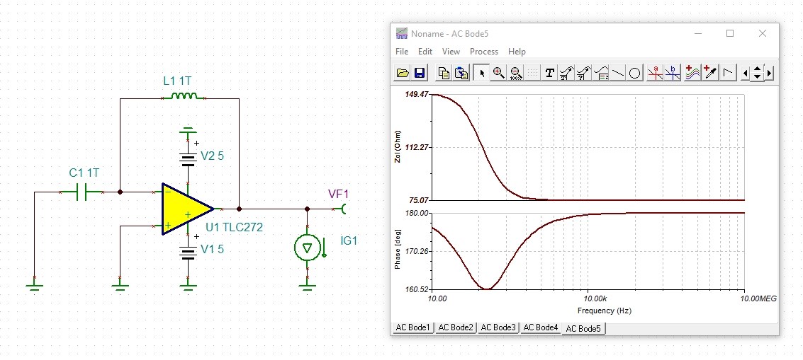
    the open-loop output impedance of TLC272 seems to be 75Ohm:

    But see this post:

    Kai

  • Thank you so much Kai for your response. 

    I appreciated it. 

    Now I have only OP2325 to go.

  • Hi Arti,

    the datasheet of OPA2325 will answer all your questions :-)

    Kai

  • Not really. I've got the output impedance, but the input impedance is still missing.

  • Well, according to the datasheet of OPA2325 and according to what Daniel already said about the ultra low input bias currents, the input impedance of OPA2325 is also in the TOhm range :-)

    Kai

  • Former Member
    0 Former Member in reply to Arti Sukasem

    Hi Arti,

    You can also estimate the input impedance based on the input bias current versus common mode range.  This is provided in the OPA2325 data sheet as shown below.  The change in voltage over the change in current will give you an estimate of the input resistance in that range.  As Kai has pointed out and as you will see if you do the math, if your Vcm is around mid-supply then you should get an input resistance in the tera ohm range.

    Regards,

    Daniel

  • Hi Daniel,

    Thank you so much for clarifying it. I had no idea how the input impedance and the power consumption can be calculated, and you taught me.

    Regards,

    Arti

  • Former Member
    0 Former Member in reply to Arti Sukasem

    Hi Arti,

    I am happy to help.  Please let us know if any further help is needed.

    One thing to keep in mind is that this is more of a method for determining the input resistance than the input impedance, since these are DC measurements.  For the AC, you need to also keep in mind the input capacitance, which will be specified in data sheet.  This is more of a question for stability than the input signal.  So, I don't want to muddy the water and cause confusion.  Just wanted to point this out.

    The bottom line is that the input impedance is very high and that the bias current into the amplifier is really more informative.  However, we can use this curve to estimate our input resistance.

    Regards,

    Daniel