Other Parts Discussed in Thread: OPA855
Hello
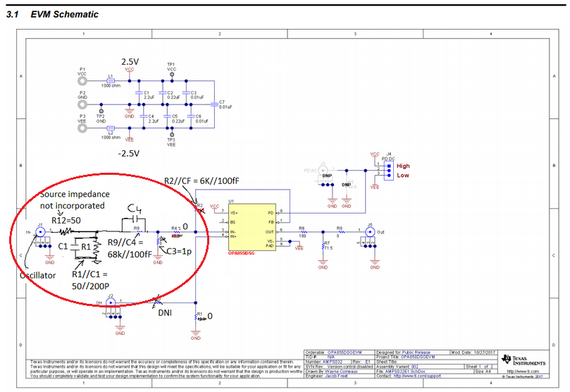
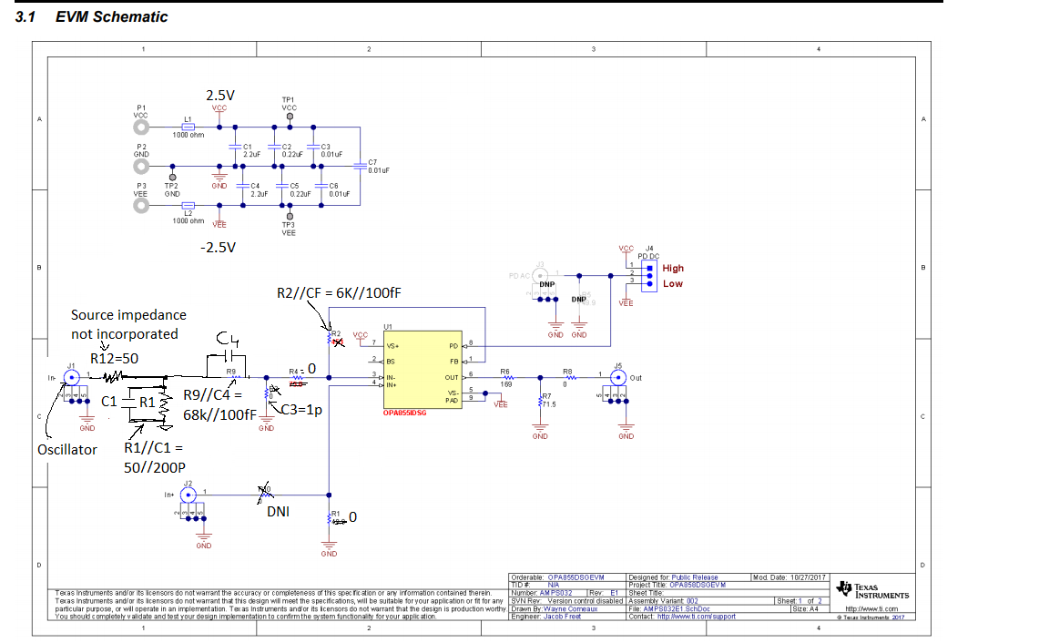
I have tested a Transimpedance amplifier on OPA855DSG evaluation module having a bandwidth of 380MHz with a gain of 6K. The transimpedance amplifier employs OPA855 and feedback resistor and capacitor of 0402 SMD values 6K and 100fF capacitance respectively. I am using a photo diode having a capacitance of 1pF. But when I performed the simulation, the system looks stable having a phase margin of 58.82 degree. But when I built the same circuit on EVM my experimental results are not matching the simulation results. The following are the problems that I faced.
- I have selected a feedback resistor R2 of 6K and the value of feedback capacitor was found to be 100fF. First I have assumed that the 6k resistor (0402) has a parasitic capacitance of 100fF. So when I did not connect any capacitor in my feedback path, the gain on the EVM circuit was not reduced.
Secondly, when I connected the feedback capacitance of 100fF then, my system became unstable with a high gain peaking and bandwidth reduction. I don’t understand how to add the 100fF capacitor in my circuit. My experimental results of the voltage gain with 100fF on EVM test circuit is shown below :
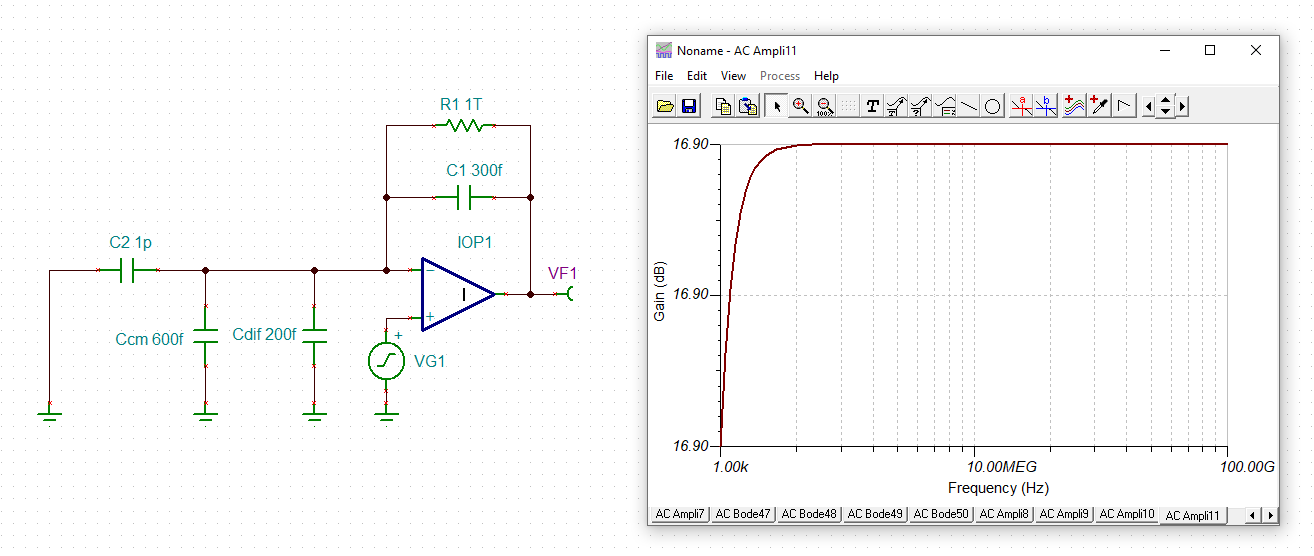
2. I have connected the ac analysis circuit on the EVM, but I am not sure that the input side of the circuit is working correctly as a current source. I have taken the reference from 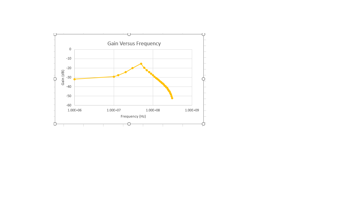
 evaluation board_AC test circuit.TSCStabilty Check_pb.TSChttps://e2e.ti.com/support/amplifiers/f/14/p/293655/1038541#1038541
Please help me understand on how to make the feedback capacitance equal to 100fF. Also please check my AC analysis circuit on the EVM.