This thread has been locked.

If you have a related question, please click the "Ask a related question" button in the top right corner. The newly created question will be automatically linked to this question.

AFE031: AFE031 SPI Control Register Question

Part Number: AFE031

Based on the data sheet of AFE031,  "A host SPI frame consists of a R/W bit, a 6-bit register address, and eight data bits. Data are shifted out on the falling edge of SCLK and latched on the rising edge of SCLK.".

So for Control Regsiter, MCU need to send 15-bit or 16-bit? On the data sheet, for Command Register, the address have 7-bit, ADDR14-ADDR8. So the address is 6-bit or 7-bit; if 6-bit, then the address should be ADDR14-ADDR9 or ADDR13-addr8? I am confused.

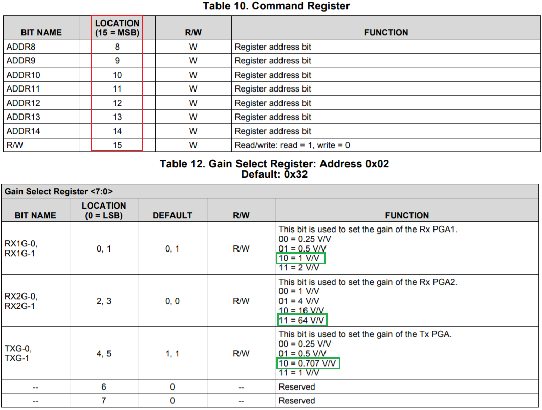
Table 8. Command Register
LOCATION    BIT NAME (15 = MSB)   R/W   FUNCTION
ADDR8              8                                  W     Register address bit
ADDR9              9                                  W     Register address bit
ADDR10          10                                  W     Register address bit
ADDR11           11                                 W     Register address bit
ADDR12          12                                  W     Register address bit
ADDR13          13                                 W      Register address bit
ADDR14         14                                  W      Register address bit
R/W 15           W                                Read/write: read = 1, write = 0

datasheet.octopart.com/AFE031AIRGZT-Texas-Instruments-datasheet-17726588.pdf

  • Hi Jimmy,

    Please use the latest datasheet, though the control register parts are unchanged. 

    https://www.ti.com/lit/ds/symlink/afe031.pdf?ts=1595520664779&ref_url=https%253A%252F%252Fwww.ti.com%252Fproduct%252FAFE031

    https://www.ti.com/lit/an/sprac94c/sprac94c.pdf?ts=1595521077108&ref_url=https%253A%252F%252Fwww.google.com%252F

    For instance, 

    if you want Write, Address= 0x02 and Data 0x32, here is what you need to send.

    bit 15 in 1=Write in MSB

    bits 8-14, address = 0x02 or 0000010 in 7 bit register address (if you count 0-6 bit, It is inconsistent to next phrase 8-bit data)

    bits 0-7, Data, default = 0x32, Let us if you want to set Rx PGA1=1V/V (10b), TX PGA2=64V/V(11b) and Tx PGA=0.707V/V (10b), then data should be sent in 

    00011101b, where 00 in bits 6 & 7 are reserved, next two bits in 01b (0.707V./V settings) represents bit5=0 and bit4=1, , next two bits in 11b for bit3=1 and bit2=1, Then two lowest bits are 01b(1V/V setting), where bit1=0, bit0=1. I prefer to write out in hex format in 1Dh for data. (pay attention to bit position definition in the each table). 

    If you have another questions, please let me know. 

    Best,

    Raymond

  • Hi Raymond: 

    Thanks! The AFE031 can be controlled properly now. But now we have a new issue. We put our board inside an oven, and when the board temperature reached 104C, the REF2 output dropped to 0.67V. Normally, it should be 1.67V which is half of the Supply. It seems that AFE031 got latched up and cannot be controlled anymore. Only power cycle can get the chip out of latch up. PA section is not used in our application, The PA supply is connected to Ground on our boards. What is the root cause? Based on the dat sheet, this chip is supposed to work up to 125C.This happens on 7 boards out of 10 boards. Does certain batch of AFE031 have this use?

    Your help is very appreciated!

  • Hi Jimmy,

    Are you doing HALT/HASS types of evaluation? What types of oven did you use (are there air current flow inside of the oven)? What is operating current of AFE031?

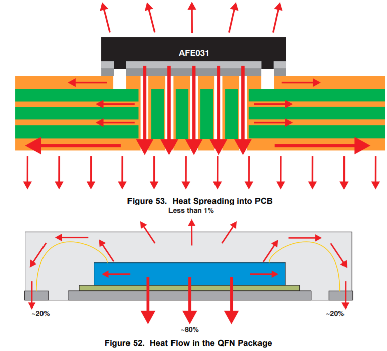
    Did you follow the layout recommendation from the datasheet? In Control2 register in Table 15 of the datasheet, there is T_FLAG_EN bit, did you monitor the bit state during thermal testing. I assumed that there are no heat sink on top of AFE031. Are you able to share the schematic with us, unless it is the reference design (pls tell me which one)?

    I can attempt to calculate what is die's junction temperature, if you provide me with testing information. Without these testing details, I am unable to provide you with answers.

    Best,

    Raymond

  • We did heat test of our board which the temperature is from 0C to 125C. Yes, there is air current flow inside the oven. We did not measure the current of AFE031, but since PA section is not used and PA power supply is tied to Ground. So the power consumption of AFE031 is low, the temperature increment is small.

    We did not enable T_FAG-EN bit. No heat sink at the top of the chip.

    At ambient temperature, the board worked well, REF2 was 1.67V all the time. We monitored the board temperature. But when the temperature of the board reached 104C, AFE031 started to behave abnormally, REF2 dropped to 0.67V from 1.67V and never go back to 1.67V even we reduced the temperature to 25C, only power cycle can make REF2 go back to 1.67V. This happed on 7 out of 10 boards.

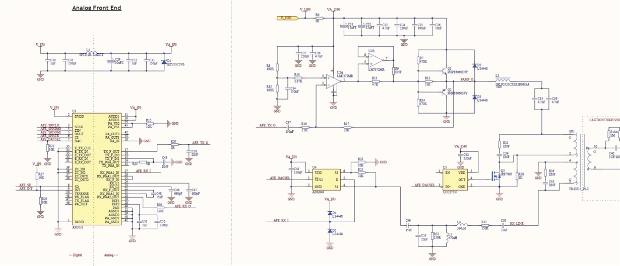
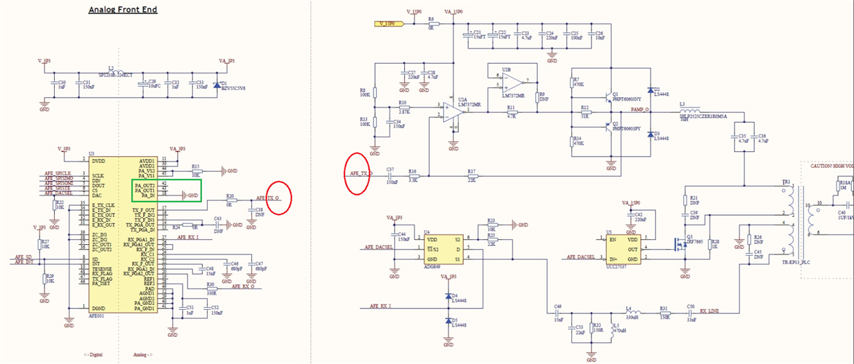
    The attachment is the schematic.

  • Hi Jimmy,

    Ok, So I assumed that the chamber temperature accuracy or uniformity is approx. is approx. +/-2C or so. I just need to verify. 

    At ambient temperature, the board worked well, REF2 was 1.67V all the time. We monitored the board temperature. But when the temperature of the board reached 104C, AFE031 started to behave abnormally, REF2 dropped to 0.67V from 1.67V and never go back to 1.67V even we reduced the temperature to 25C, only power cycle can make REF2 go back to 1.67V. This happed on 7 out of 10 boards.

    I need to get back to you on this one. I did not see any loading on pin28 from schematic, which is used to generate Ref2, except 1uF and 150nF capacitors. Are you simply monitoring the voltage at pin 28 during thermal test? Or is there any load connected to the pin28?

    Can you clarify the following statement? "AFE031 started to behave abnormally"

    Did you observe other abnormal behaviors when the IC temperature reached 104C? Or simply Ref2's output voltage is acting up, and latched up per the observation. Do you know that PA's output is working properly?  

    Can you remove 1uf and 150nF capacitors from pin28, if you are doing thermal temperature test again next time? In Figure 36, it is recommended 1nF filtering capacitance. I know that the datasheet on the bottom of p.14 is recommending 1uF at pin28 and 1nF at pin19, which I believe that is a typo. 

    Can you also send me the lot information (the marking on the AFE031, including the working ones)?

    Best,

    Raymond

  • Hi Raymond:
    We did not load REF2. It was just hooked to Oscilloscope for monitoring purpose, the probe input is High impedance91MOhm).
    AFRE031 started to behave abnormally means that REF2 voltage dropped to 0.67V from 1.67V and the TX output at Pin 17 (TX_F_OUT) became very small, and the communication was lost.
    We put a thermal coupler at the top of the AF031 and the temperature was around 107C. 

    Below is the information (marking on the AFE031). The marking of good one and bad oneis the same.

    AFE031AI

    TI 87I

    AVTG G4

  • Hi Jimmy,

    Ok, thanks for the information. 

    I was paying attention to Ref2 in the previous replies. I noticed something that is strange in your schematic, whch TX_F_OUT is driving to the transformer's output. This is not correct.

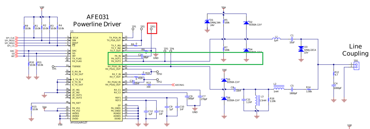
    AFE031 is built in with power amplifier in the circuit. TX_F_OUT pin should go into PA_IN (power amplifier's input, AC coupled), PA_OUT1/PA_OUT2 are the power amplifier's output and drive the rest of transformer coupling circuit. 

    Enclosed is the AFE031 EVM application note. 

    https://www.ti.com/lit/ug/sbou223/sbou223.pdf?ts=1596475590878&ref_url=https%253A%252F%252Fwww.google.com%252F

    Please tell me what you are trying to do in your schematic. TX_F_OUT pin does not have the power (voltage or current) to drive the output. Our AFE031's design is different from some of our competitors. AFE031 has built in with various discrete Tx, Rx and PA stages to insure impedance matching, flexibility configuration  and driveability for the PLC application. 

    BTW, place a load at the output of PA_OUT1 and PA_OUT2 (1kOhm or so), if you are testing the AFE031 only. 

    If you have questions, please let me know. 

    Best,

    Raymond

  • Hi Jimmy,

    Please let us know if your thermal latch issues are resolved. 

    My guess is that the test test up is loaded down Tx pin that is not designed to be loaded down in this manner. Our customer is running a lot higher temperature than 107C in AFE031 sometimes, and it works fine.

    BTW, TI PLC ICs have better thermal characteristics and performances than our competitors. 

    Regarding to the marking below, the part is manufactured in July, 2018. 

    AFE031AI

    TI 87I

    AVTG G4

    Best,

    Raymond

  • Hi Jimmy,

    Please let us know if you need further assistant in thermal tests. 

    I am going to close this inquiry. You may still reopen the case or open a new one, if you have additional questions. 

    Best,

    Raymond

  • Hi Raymond:

    Thanks! We will replace this batch of AFE031 and see if can solve the issue.

    You can close this inquiry.

    Thanks!

  • Hi Jimmy,

    If you are encountering additional thermal latch or any other issues in AFE03x products, please let me know and I will help you to find the root causes. I am the application engineer who is supporting the AFE03x product lines. 

    Thanks,

    Raymond