This thread has been locked.

If you have a related question, please click the "Ask a related question" button in the top right corner. The newly created question will be automatically linked to this question.

operational amplifier for relè

Other Parts Discussed in Thread: L293D, DRV8837, DRV8837C, LMV862

Ciao a tutti.
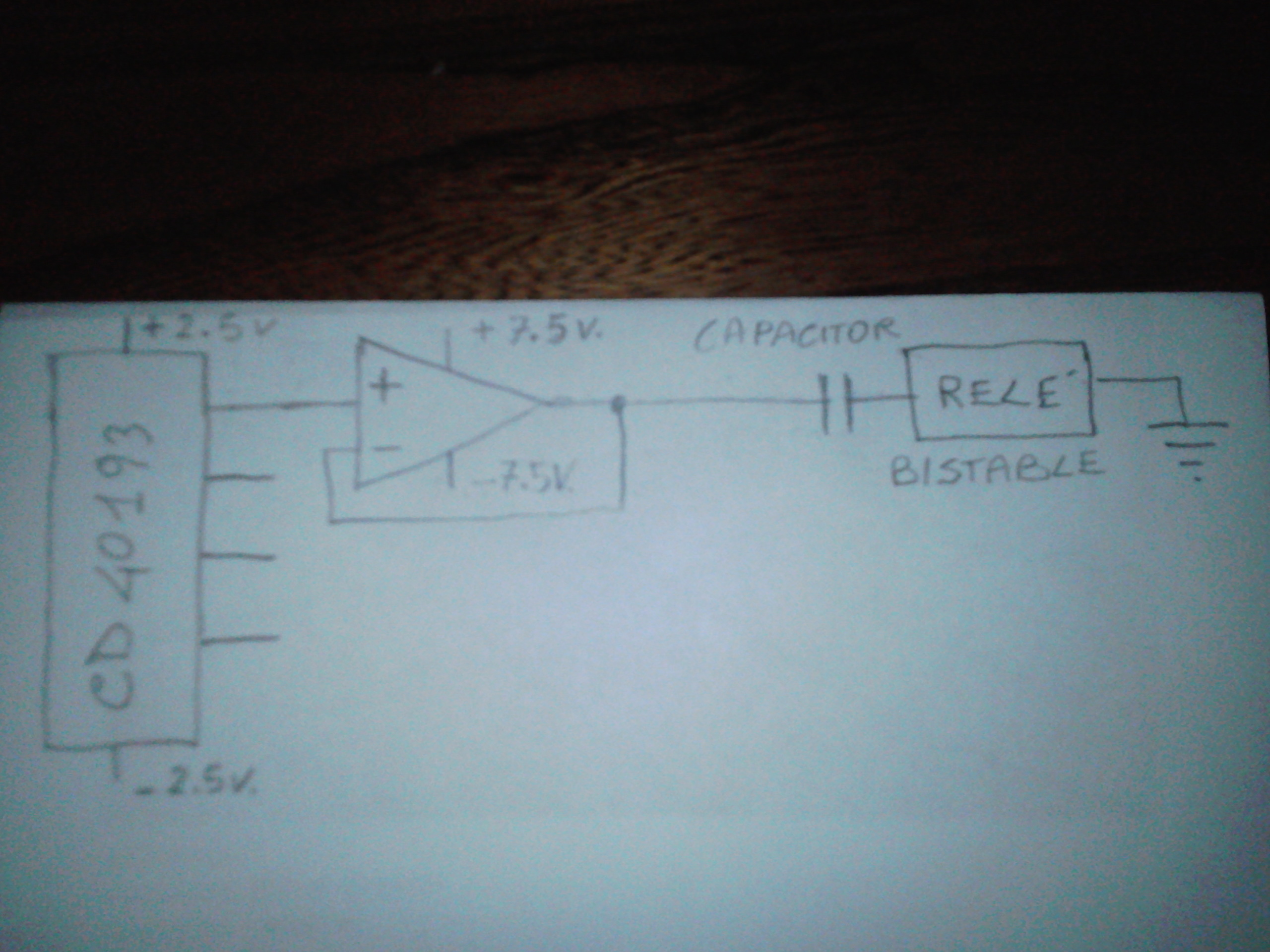
sono alla ricerca di amplificatori operazionali in grado di pilotare sei relè bistabili a bobina singola, non tutti insieme ma separatamente. in questi relè la corrente scorre in entrambe le direzioni.
Ho bisogno di amplificatori operazionali in grado di sopportare la corrente necessaria (un impulso) ma soprattutto la sovratensione generata dalla bobina del relè quando è spenta poiché non posso applicare un diodo di protezione in parallelo alla bobina del relè.

  • Hi everyone.
    they are looking for operational amplifiers capable of driving six bistable single coil relays, not all together but separately. in these relays the current flows in both directions.
    I need operational amplifiers able to withstand the necessary current (an impulse) but above all the overvoltage generated by the relay coil when it is turned off since I cannot apply a protection diode in parallel to the relay coil.

  • Ciao Luigi,

    can you tell some details on the relais? Does each relais consist of two seperated coils? Do you have a datasheet?

    Kai

  • no . these relays only have one coil but the current flows in both directions.
    I have not yet chosen which relay but I think the amount of current in mA is similar to that of the other relays.

  • Hello Luigi,

    If you have a dual supply where each half has enough voltage to run the relay then a push/pull peripheral driver would work well. With a single supply an H driver is needed. H driver is more common. For low cost there is DRV8837. For easy PDIP testing there is L293D. 

    This could be done with an op amp, just like a wrench can be used as a hammer.

  • Hi Luigi,

    In addition to the DRV8837, the DRV8837C is another option available.

  • thanks for the replies. the H bridges that I know need at least two distinct commands but I have only one (high or low state deriving from the outputs of the 40193) which is why I had thought of an operational amplifier configured as a buffer. of course I had already thought of making a dual power supply with a central socket transformer and a double capacitor voltage divider in order to supply power to the two 40193 (5 volts) and operational amplifiers (15 volts) whose input is connected at the exit of 40193. two 40193 six outputs that go to six operational amplifiers but what worries me is the overvoltage created by the coil at shutdown. quidi? do you recommend a push / pull? for example ?

  • Luigi,

    A bistable relay has three input states [set, clear, hold]. That takes 2 binary bits, or a trinary signal [low, center, high].  

    What does your control signal look like?

  • I don't know which type of relay you are referring to.
    maybe it's better that I attach a scheme as soon as I can

  • in a simplified way

  • Luigi,

    The capacitor divider does not work for DC loads, so your +/-2.5V will die out quickly. A dual supply is not needed unless there is need to not change the relay on power up accidently. If 5V is enough for your relay then there is no need for the 15V supply. 

    Here is a possibility for op amp LMV862 (two channels)

    VG1 is the digital input. Be sure to fully test this as I do not know your relay. I pasted the LMV862 model code into a LMV353 shell as a shortcut.

    LMV862 relay driver.TSC

  • Hello and thanks .
    I have not yet chosen the relay.
    I thought about the double power supply because the two CD40193 work together with two 74HC154 (in the scheme there are not, my fault) so I need 5 volts for sure.
    the other voltage of 15 volts that you see in the diagram is actually only indicative, having not yet chosen the type of relay, but above all I wanted to have the possibility of being able to also use relays that operate at higher voltages, in this way I can enlarge the faculty of choice without remaining anchored to 5 volts.
    there is another reason that led me to think about the double power supply, in this way I can decrease the number of components and simplify the circuit.
    if you have patience I have some questions about your circuit.
    I assume that the node between R2 and R3 serves to replace the reference potential given by the double power supply.
    it is not clear to me how you connected the relay coil.
    maybe it's parallel to the RL-L1 group?
    what function does the RL-L1 group have? , perhaps it serves to dampen the overvoltage caused by the relay coil? .
    does the capacitor C1 have the function of making the current flow in the opposite direction when the output of the operational amplifier goes to ground?
    in addition to the supply voltage of 5 volts, is there a particular reason that led you to choose this operational amplifier?

  • Luigi,

    The op amp is setup as a comparator (open loop) and R2 and R3 setup a voltage that is between the VOL and the VOH of your digital input signal.

    RL and L1 are a pretend relay. Every relay is a series resistance and an inductance (there are other lesser factors too). In other words, pull out R1 and L1 and put the relay there. 

    The LMV862 has a large output current drive capability.

  • could this work?
    do not look at values and components, the scheme only serves to convey the idea.
    5 volts for integrated CD40193 and 74HC154.
    15 volts for operational amplifier.

  • using the operational amplifier configured as comparator with R2 and R3 on 5 volts

  • Luigi,

    A different op amp will be needed for a 15V supply.

  • Hello.
    I would also like to explore other alternatives and then evaluate the best choice.
    I found the H bridges but they need two commands, but I only have one command available. how could this be done?

  • Hi Luigi,

    H Bridges do require two command inputs, but can be configured to require only one extra input than the number of relays for the system.

    This is assuming only one relay will be changed at a time.

    An example uses the PH/EN interface. The PH (direction) can be connected to all the H Bridges. The EN pin can be used to energize the relay coil, and then disable the current when the relay is set to the desired configuration.

  • Luigi,

    The only reason that the op amp circuit did not need two commands is because the series capacitor blocks continuous current flow. The cap will work in H drive in the same way.