This thread has been locked.

If you have a related question, please click the "Ask a related question" button in the top right corner. The newly created question will be automatically linked to this question.

LMP7732: Differential and Common-Mode Capacitance Value

Part Number: LMP7732
Other Parts Discussed in Thread: OPA211, OPA2810

Dear team,

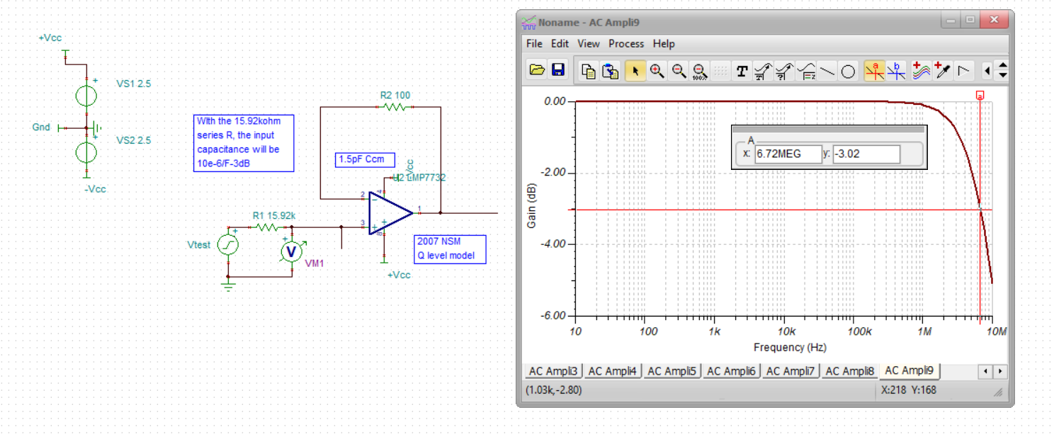
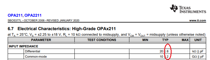
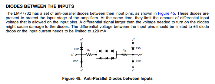
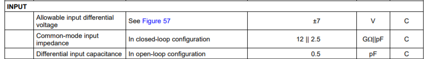
our customer is interested LMP7732. For stability analyses, the need the differential and common-mode capacitance value. However, they are not listed in the data sheet - we could only see the Input Resistance on page 4.

Can you please provide the data?

Thanks and best regards
Martin

  • Hi Martin,

    see what the Spice model shows:

    Kai

  • I was also looking into the TINA V11 model library - it has  a lot of diodes on the inputs - which, if modelled correctly, will have voltage dependent C - the ones above seem very high, was this the 7732 or 7731 model? 

    I would be betting the physical device has a very CM voltage dependent input C

  • Oh that is a 2018 updated model to the GWL template, not sure where they would have gotten those C values? 

    TINA V11 has the 2007 transistor level model with diodes and Q's. Here that is, 

    Header looks like this, 

    LMP7732 2007 model.TSC

  • When in doubt, one may easily verify the input common-mode capacitance, Cin_cm, by adding a known resistor value in front of the buffer and sweeping the input over frequency looking for -3dB frequency – see below. Then it is straight forward to back calculate Cin_cm to be 10pF.

    The differential input capacitance, Cin_diff, is more complicated to measure but as Kai pointed out it may be seen by inspecting actual netlist of the LMP7732 to be 5pF.


    The old 2007 LMP7732 macro-model does not seem to model Cin_cm and Cin_diff.

  • The old 2007 was more the transistor level model and will have capacitance as part of those models (and the diodes). 

    Dropping it into the file I was using back in that article prep simulates to 1.5pF input Ccm, much more reasonable for a 22MHz part than 10pF. 

    The eventual aim here was to test for phase margin where usually you will put Ccm +Cdiff on the inverting node after you have broken the loop, the 15pF total in the updated model will likely show issues 

    Yes, that Ccm is the easiest to measure with just a series input R - if that was done for the model update, then yes, 10pF might be right. Although measuring at the output will need to target a lower input pole than I did here to keep the op amp BW out of that measurement (higher series R). 

  • Michael,

    Yes, unlike current Green-Lis behavioral macro-model, the old model was implemented as simplified transistor level design and thus compromises and trade-offs must have been made to model different characteristics of the op amp. Thus, Ccm input capacitance of just 1.5pF might be the result of such trade-off. Our modern behavioral model does not use a single transistor and thus has no parasitics to speak of and for this reason various parameters may be modeled completely independent of each other.

    I believe the current LMP7732 macro-model Ccm and Cdiff input capacitance were actually measured to be 10pF and 5pF, respectively. Even though it makes sense to expect higher speed op amp to have lower input capacitance, LMP7732 is not a Giga-Hertz op amp. This is especially true with precision parts using trim networks at the front-end, which add a lot of input capacitance. These may be seen by looking at OPA211 having Ccm and Cdiff of 2pF and 8pF, respectively, despite having much faster 80MHz GBW.

    All in all, when in doubt, it would be simple enough for customer to just sweep the frequency of actual LMP7732 and confirming it.

  • At one time Marek, we were revalidating the Ccm and Cdiff for the whole range of high speed VFA parts. Many of them had incorrect numbers in both the datasheet and models. I seem to recall we found universally the Cdiff was lower than the Ccm - I of course then wonder about the 211 specs. Maybe if you have large area clamping diodes across the inputs, that would make more sense. high speed often has those as well, but tiny and low C. 

    We went through a couple of different lab and sim validation approaches. I think we where using a closed loop transimpedance test to pull out the Cdiff, which is the tougher one. 

    The transistor level models are usually better if the Q and diode models are thorough - when you are doing those, you need to test the device for Ccm and Cdiff and then add what you need extrinsically over what the transistors are adding. Since they did not even add a spec line, I suspect that did not happen back in the 2007 timeframe. 

  • Yes, as may be seen below OPA211 does have back-to-back input protection diodes, which increases Cin-diff.

    This is also true in case of LMP7732 (see below) and thus it is hard to believe its Cin_diff would be just 1.5pF.

    The transistor level macro-models have three major problems:

    1. Trade-offs must be made to model various op amp parameters

    2. Because of their relative complexity, they have major convergence issues

    3. Because they are based on actual IC design, it takes months to create them - long after products are released to market

  • All good points Marek, except #3. 

    Having managed many model developments, I elected in the late 80's to provided simplified transistor level models for the CLC parts. Since the apps and designers worked so closely, we could take and simplify the full design file in less than a day and provide customer models actually prior to release. Macromodels historically are more time intensive to develop. 

    There is actually a detailed app note out there showing the simplified internal schematics for many of the CLC devices - and, with model files still sitting in the TINA V11 library you can match them up completely with the netlist - you can't buy them anymore, but the modeling is still out there. 

  • And frankly Marek, if in fact the model update went to the effort to remeasure an unceartain input C, I would have expected the data sheet to capture that info. I am thinking not, no data, lets put in a fill number. 

  • Micheal,

    You are right that in an ideal world that's what should have happened.

  • All,

    thanks a lot for the answer and the great explanation of the background!!

    I can work with the values of the simulation model and we can confirm it later with model itself!

    Best Regards
    Martin

  • So Martin, if you actually set up and try to measure the V+ input Ccm, one of the long running spec gaps has been that input C over input common mode voltage. There really should be a plot of that to warn people of dangerous stability areas as that C changes - for all those RR input parts with crossover networks, what does that C look like over the input range. A design that is stable at midscale, might slip over into trouble towards the positive rail? 

    I kind of ran into this operating point stability issue long ago with the CLC300. It had a very simple output stage that was very V/I dependent on prop delay, you really don't want a call from the Grateful Dead audio folks saying it works most, but not all, of the time. 

  • Hi Michael,

    I always double the input capacitances in my personal stability analysis. Would this fully take the input capacitance variations over common mode input voltage into consideration?

    Kai 

  • Well Kai, I actually don't know, but if you look at a part like the OPA2810 which has quite an involved input stage over CM, it would be an interesting test. Some of those input crossover network type parts talk about the input offset voltage shifting with operating region - I have not seen any show a Ccm vs Vcm plot. And maybe it is dominated by package parasitic and the active device portion does not add much? 

    Anyway, here is the OPA2810 input impedance - that open loop comment on the differential input C is unnecessary. If you are running a transimpedance test, you add Ccm + Cdiff to the diode C for solution. that is closed loop, really misleading to say open loop for the Cdiff. However, this is showing what we found generally - the Cdiff < Ccm. These C's look very reasonable,