This thread has been locked.

If you have a related question, please click the "Ask a related question" button in the top right corner. The newly created question will be automatically linked to this question.

TLV9064: Current to voltage conversion

Part Number: TLV9064

Hi sir,

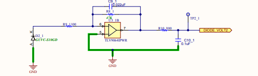
we have one readymade board, which is used to convert the current to voltage conversion using a TLV9064 op-amp. I need to measure the current from the photodiode. As per the datasheet, whenever there is no light condition, it will produce 100uA current, but I can't able to measure the equivalent voltage. as of now, we don't have UV-A light source, so we can't validate the circuit. Please advise me, if any update required in this circuit.

  • Former Member
    0 Former Member

    Hello Vignesh,

    Thank you for your question.  Would you please try to re-attach your image to this thread so I can see the circuit?  It seems to have failed to upload.

    Regards,

    Daniel

  • Hi sir, 

    Due to technical issues, the Image was missed from the earlier attachment. So please find the attached document for your reference. 

  • Former Member
    0 Former Member in reply to vignesh M6

    Hello Vignesh,

    If there is no light, then the diode should produce 100uA of current.  Am I understanding correctly?  In such a case, the 100uA of current would travel through the 47kOhm feedback resistor to create a voltage of 4.7V at the output of the amplifier.  This will be ok if we assume that the amplifier is using a single-supply of 5V at V+ and GND at V-.  Although, you should note that if the diode gives more current when there is more light then the output of the amplifier will rail to the V+ voltage.

    However, your In+ pin is tied to GND.  It is not a good idea to tie one of your inputs directly to the rail as this will also cause the amplifier to want to rail at the output.  Please let me know if this does not make sense.

    You may also find this resource helpful.  Download the e-book for amplifiers and go to page 265.  There is an example of how to design this type of circuit that you may find useful.

    Regards,

    Daniel

  • Former Member
    0 Former Member in reply to vignesh M6

    Hi Vignesh,

    I hope you have made some progress working toward a resolution for your issue.  We haven't heard back from you in while, so perhaps that is the case.

    Please let me know if I can do anything else to help.  Else, I will assume that the matter has been resolved.

    Regards,

    Daniel