This thread has been locked.

If you have a related question, please click the "Ask a related question" button in the top right corner. The newly created question will be automatically linked to this question.

XTR111: XTR111 vs Howland CP - frequency response

Part Number: XTR111

Dear TI Masters,

I'm looking for a voltage to current converter, able to provide 0 to 28mA output current.

In an earlier post, this was answered:

How about XTR111?
It can support up to 36mA with the external MOSFET.

Or you can consider the Howland current pump circuit with opamps, referring to the below application note.
http://www.ti.com/lit/an/snoa474a/snoa474a.pdf
If you ere interested in this circuit, I would recommend INA592 and OPA192.

Thank you and Best regards,
Iwata Etsuji

Will the XTR111 with external mosfet have a good response for frequencies up to 40kHz, or for this frequency should I follow the Howland current pump suggestion?

Thanks!

  • Hi Vitor,

    The XTR11 only has a current output specified from 0-25mA. There is derated performance up to 36mA. Page 8 of the XTR11 datasheet shows that the device has lower linearity when used from 0-36mA. This may or may not be important to you. The bandwidth of the XTR111 will support 40kHz as seen in Figure 3 on page 6 of the datasheet. However, there are some noise spikes that are introduced after 10kHz as seen in Figure 6. You can add low pass filtering on the output to reduce the effects of this introduced noise.


    Best,

    Katlynne Jones

  • Hi Katlynne,

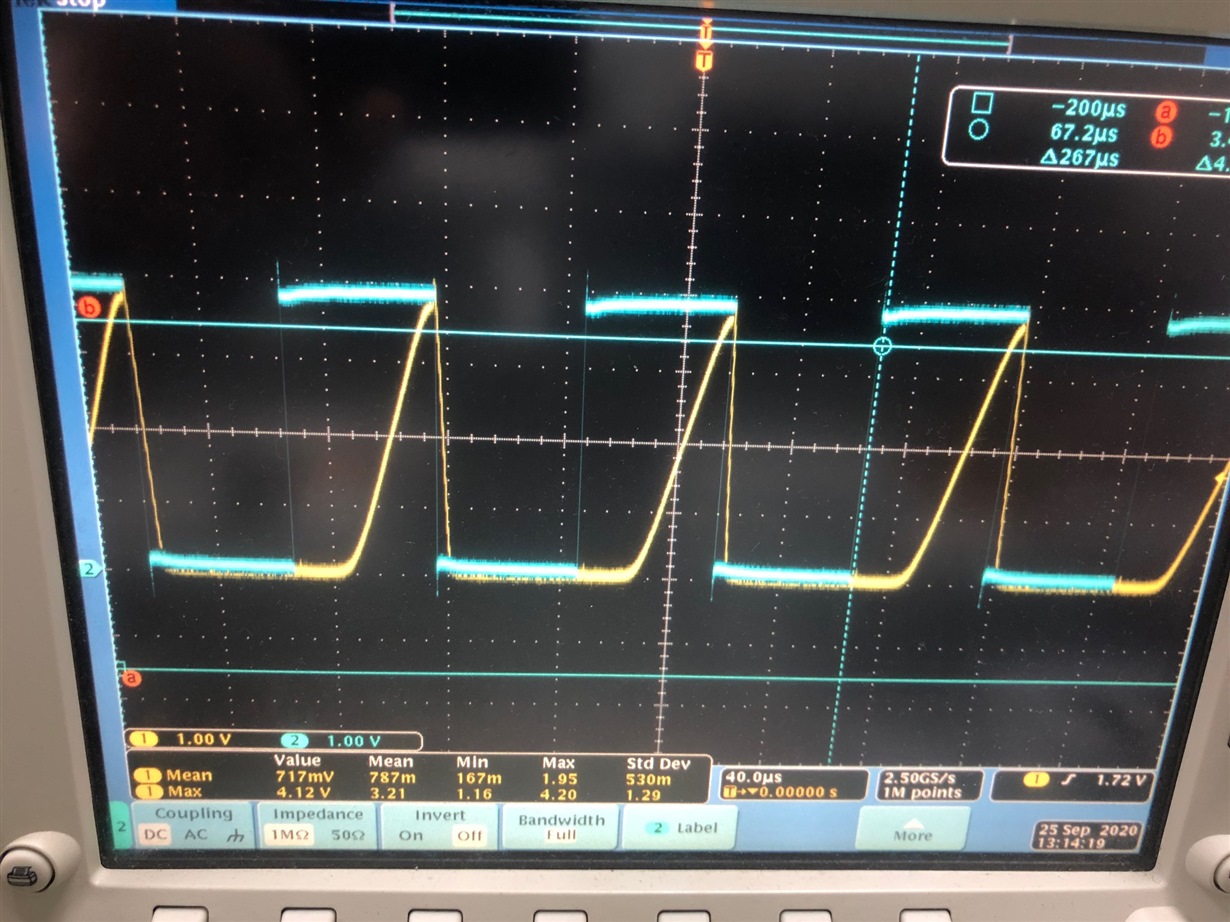
    I ordered a XTR111EVM in order to make some tests with a square wave input and I see that at 10kHz the voltage output is like in the picture bellow. The blue line is the input and the yellow one the output voltage pin.

    Is there something I'm missing in order to get a better response at higher frequencies?

    Thanks!

  • Hi Vitor,

    The XTR111EVM is primarily optimized for DC precision. The configuration on the EVM filters the ripple noise and is not an optimal configuration for high slew rate and high frequency applications. On the EVM there is a 10nF load which will slow the slew response, diodes D1 and D3 may be adding some parasitic capacitance that could also be slowing the slew response, and then the gate capacitance of Q3 on the EVM is typ 328pF, max 410pF.

    Figures 31 and 32 of the XTR111 datasheet show the slew response to be about 10us with a gate capacitance of 130pF. This difference in gate capacitances does explain why the slew response is slower on the EVM (about 3 times higher). If your goal is to use this device with 40kHz signals, the ideal 10us slew response seen in the datasheet might still be too slow for you.

    Best,

    Katlynne Jones