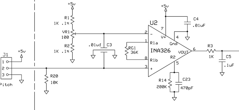
I have the following circuit without R20, the 10K resistor to ground. Occasionally the output upon power sticks to the 5V rail. I've never had this problem before, but use this circuit at much higher gains. The gain is set at 11.1X.
The input is from a Hall sensor, but substituting a 10K resistive pot produces the same problem. Can someone help me understand why this is happening and what I can do to fix it?
Thanks in advance.