This thread has been locked.

If you have a related question, please click the "Ask a related question" button in the top right corner. The newly created question will be automatically linked to this question.

LMH32401RGTEVM: Ringing in output of LMH32401

Part Number: LMH32401RGTEVM
Other Parts Discussed in Thread: LMH32401, TINA-TI, OPA857, OPA857EVM

Hi,

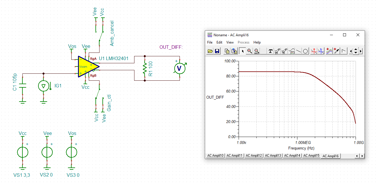
I am evaluating the part LMH32401 for use in my LIDAR system (TOF type). I generate a laser pulse of pulse width 20 ns periodically from a laser driver board, then bounce it off and I am trying to use the LMH32401 demo board as a receiver. 

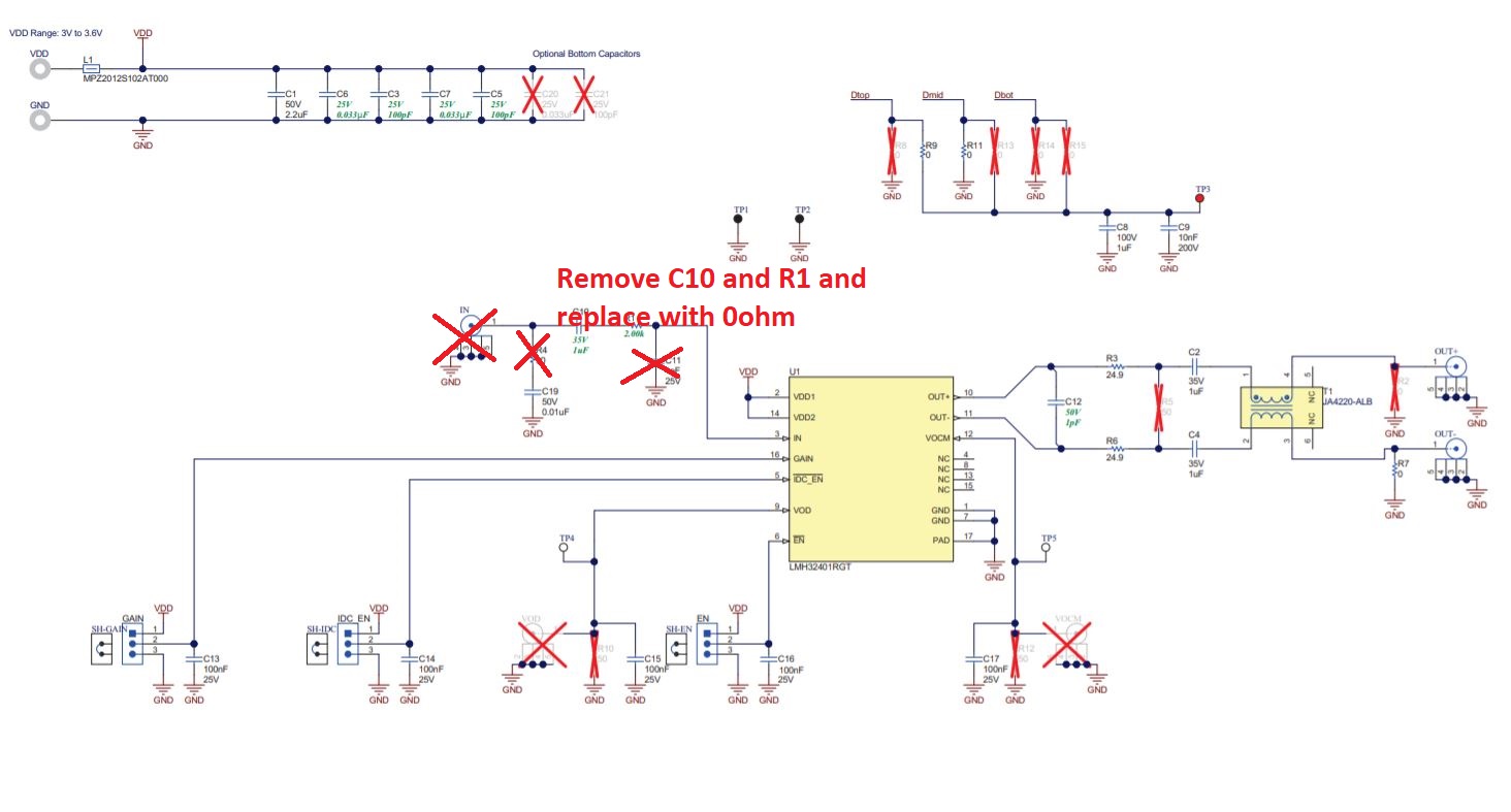
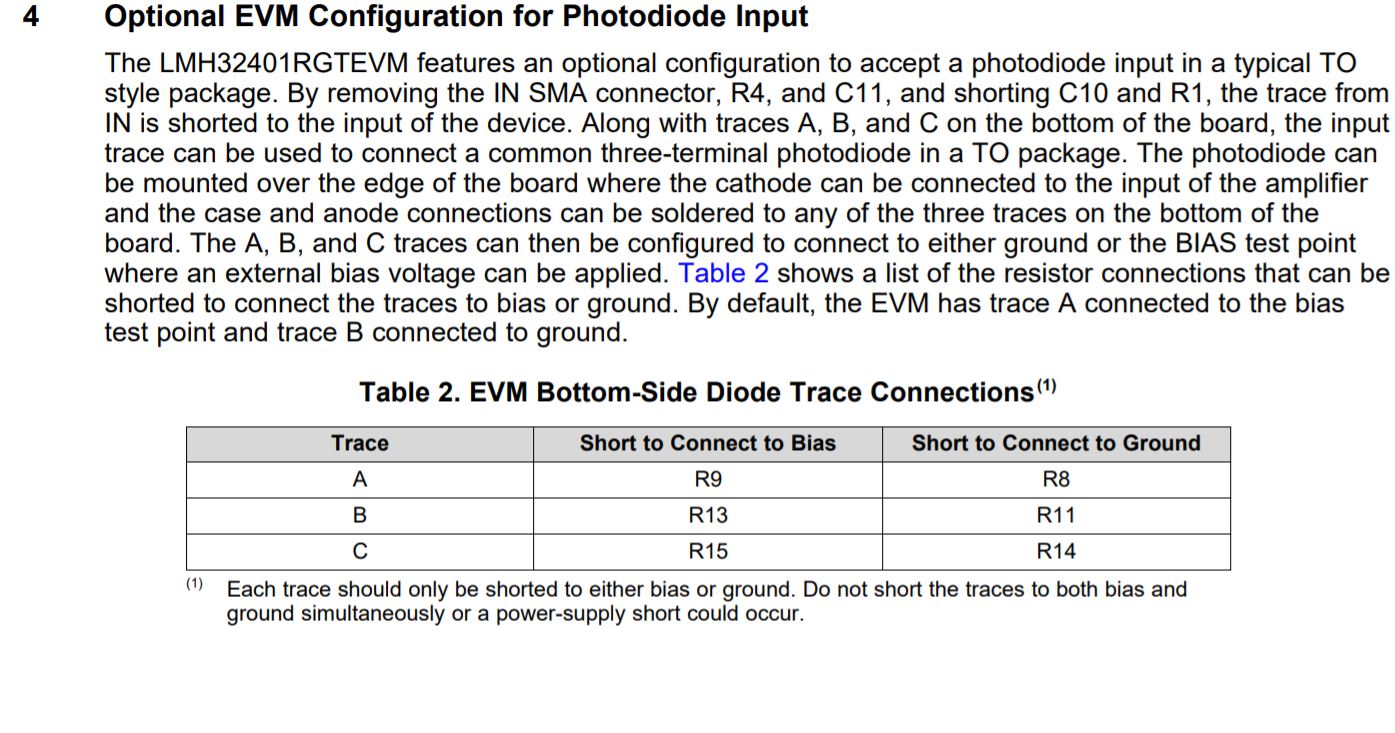
I have soldered an avalanche photodiode ( part no.APD50-8-150, OSI optoelectronics make), Cpd = 105 pF to the EVM. The anode is connected to -160 V bias(generated from a DC-DC converter) and the cathode is shorted to the IN port of the evaluation board. So the photodiode is in current sinking mode. The IDC_EN pin is set to LOW to enable cancellation of the DC ambient light.

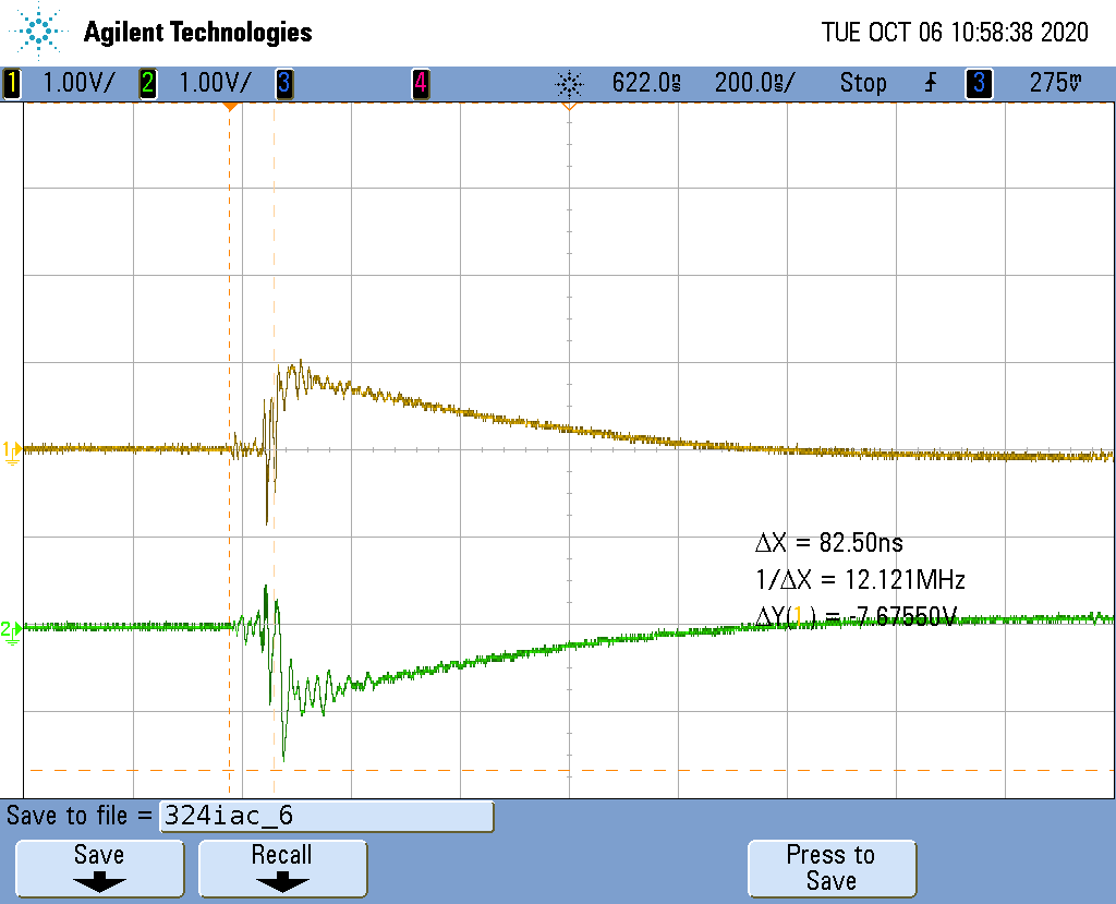
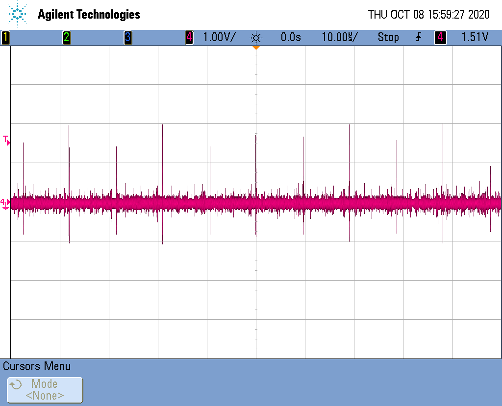
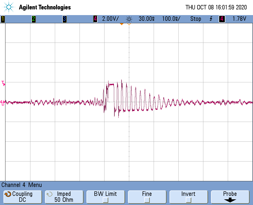
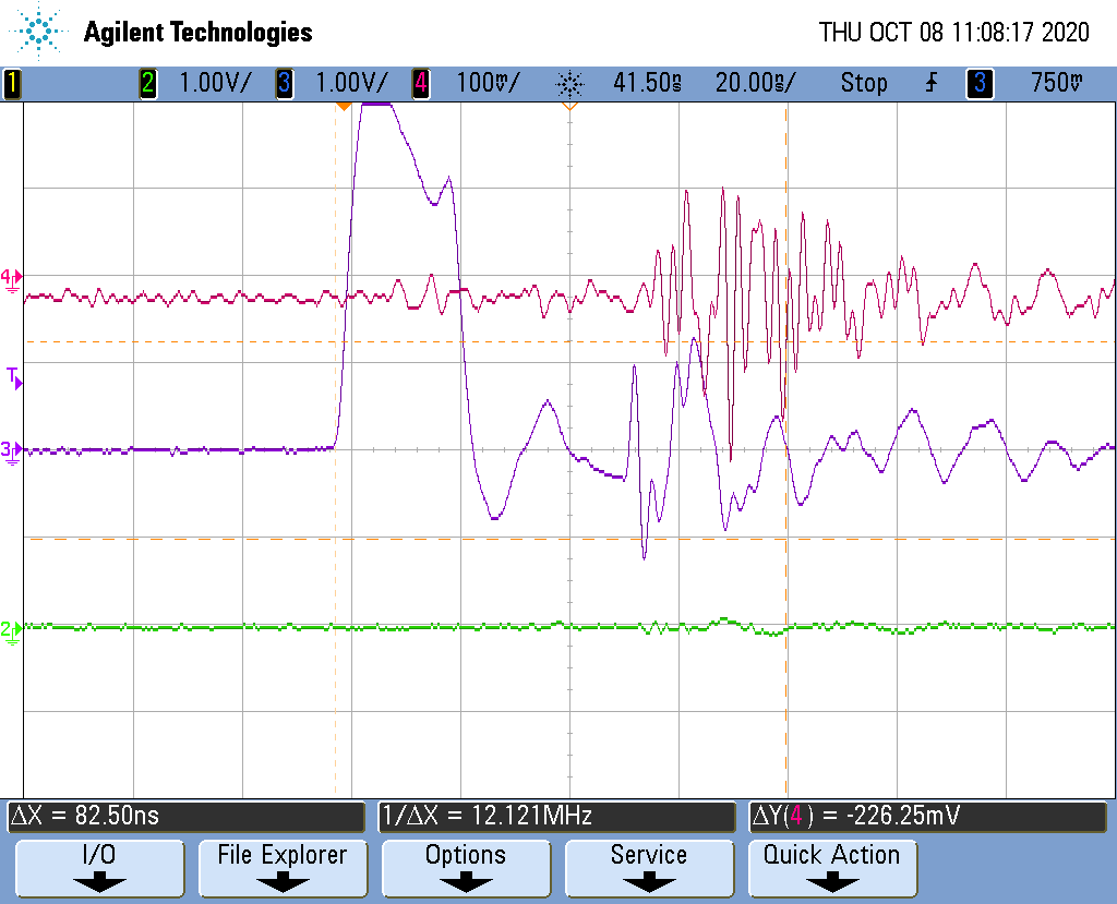
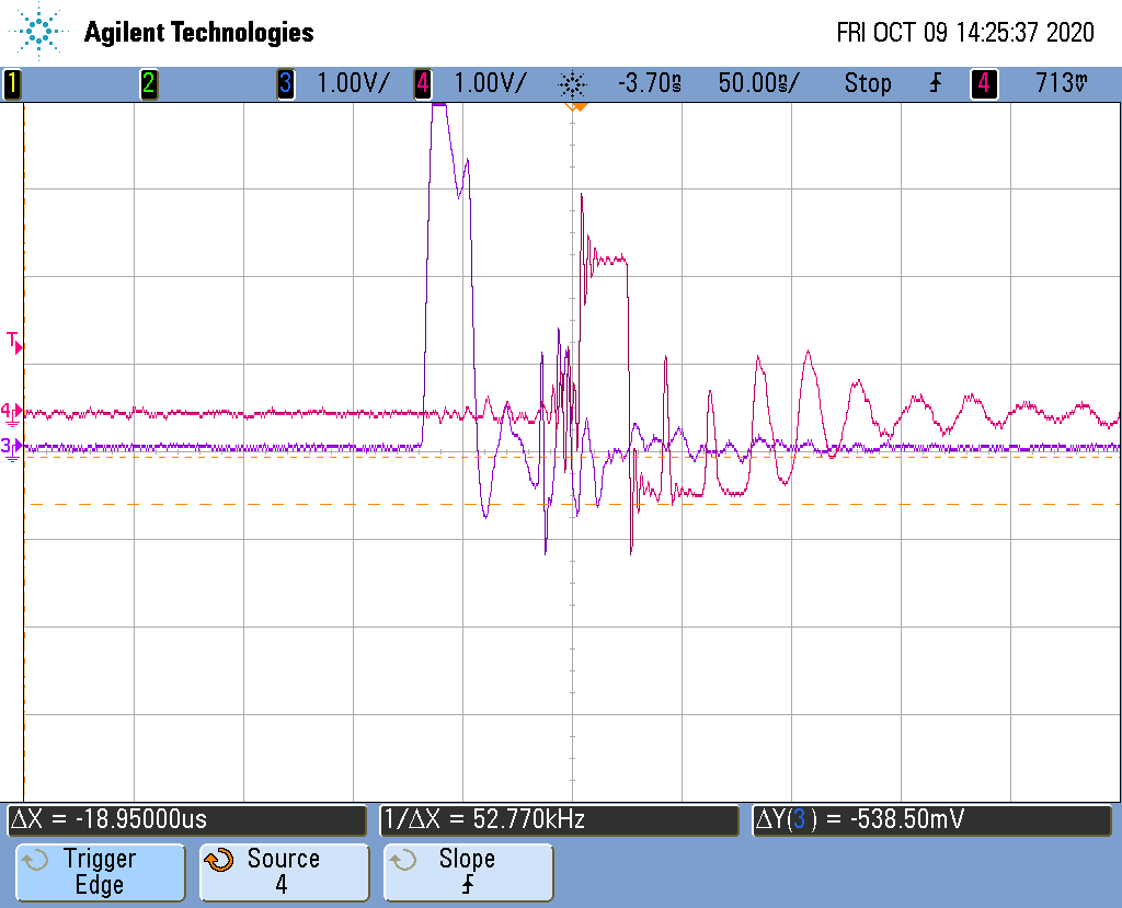
When I fire the pulses to a reflecting target and try to capture the pulse with the EVM, I am getting oscillations on the rising edge on both the inverting and non-inverting output. The AC coupled differential output also has the same ringing on rising edge of the pulse.

I intend to connect the output of the EVM to a comparator to generate pulses which will be given to a TDC ( time to digital converter) for time delay measurement to be converted to distance.

When I do so, I get multiple pulses because of the ringing. Can someone please help me in eliminating the ringing.

  • Hello Krishna,

       Thank you for the detailed description of your setup. Would you also be able to provide scope shots of the ringing and some of the other amplifier settings such as the gain selection, VOD, and VOCM? From first glance, it looks like your Cpd is a bit high (datasheet has performance specified at an input capacitance of 10pF), and might need to be compensated at the feedback with some capacitance to stabilize the amplifier. 

    Thank you,

    Sima

  • Hello Sir/madam,

    the following are my settings : VOD shorted to GND, Vocm pin connected to capacitor to GND, GAIN = HIGH ( 20 k) , IDC_EN = LOW (enabled). The following scope screenshot is of OUT+ and OUT-,both AC coupled. This is sensed after the transformer.

    The following scope screenshot shows the differential output waveform (Red color) captured with 50 ohm differential probe.

    Please let me know what I need to do to eliminate ringing.

    Thanks ,

    Krishna

  • Hello Krishna,

          Thank you for the scope shots. I am looking into this issue of instability when using a high input capacitance and will get back to you by 10/08. The TIA within the LMH32401 can not be compensated the normal way (adding a feedback capacitor) since it is internal to the device. In the meantime, would you be able to test with an APD with a lower input capacitance around 1-10pF?

    Thank you,

    Sima

  • Hi,

    The earlier scope screenshots were with the 10 Kohm inbuilt series resistor in the eval kit ( sorry for not mentioning earlier!). The following scope screenshots are taken across the OUT+ and OUT- pins of LMH32401 , differentially, with 50 ohm differential probe connected to 50 ohm input of oscilloscope, with DC coupling.

    With the 10Kohm resistor removed between the APD and the IN pin of LMH32401 the output waveforms are as follows :

    1. With laser not powered ON :

    There are nearly 2V spikes occuring almost every 10us.There is no ambient light. The test was performed in dark room. This could be some noise either coming from the amplifier or amplified noise sent by APD.

    2. With laser fired, the following is the scope screenshot :

    As seen from the above picture , the amplifier saturates but there is a decayed ringing.

    When we put a series 12kohm resistor, the amplitude ringing becomes small, about 500 mV p-p. At that time the edges of the reflected pulse become visible and bigger than the oscillations. But the edges have some small sinusoidal fluctuations.

    Please provide a suitable solution to this issue.

    Thanks.

    Krishna

  • hi,

    As I don't have a low capacitance APD, I tested the eval board with PIN diode (part no. SFH2400FA, OSRAM make). This part has Cpd of 4-5 Pf at 5V of bias.

    I connected the anode to -5V and the cathode to the IN pin of LMH32401. Again, diffrential measurement is done with 50 ohm differential probe, DC coupled to 50 ohm oscilloscope input channel.

    the following is the screenshot :

    The pink waveform ( channel 4) is the differential output of LMH32401. The electrical input to the laser driver is shown in blue ( channel 3).

    We found out that the initial ringing on the output of channel 4 is due to EMI noise coming from the laser driver during switching. However when exposed to laser light , there is no pulse at the output. Only the above ringing is present.

    When we tested with another TIA (AD8015) , we got the same output before the laser was turned ON. After the laser was turned ON, we got the same sine waves riding on top of the pulses.

    I hope this information helps. Please let us know of a way to resolve the issue.

    Thanks,

    Krishna

  • Hello Krishna,

      Thank you for the further tests; it was helpful. It seems like it might not be a high input capacitance problem which was the initial thought for causing the amplifier to be unstable and oscillate. Also, a design engineer further confirmed that an input capacitance at 105pF didn't produce any evidence of ringing in design simulations for the LMH32401. Looked more into your setup with your addition note for a 10k ohm resistor between the APD and the input of the EVM, and ran into some questions there. Since you are using an APD/diode, there shouldn't be any of the resistors/caps in between the APD/diode and the input of the device itself (LMH32401 input pin). The resistor is there to convert a voltage input to a current input; since you are providing a current source, there is no need for these additional components. I see that the amplifier saturates when you do remove the resistor, why not use the lower gain setting in this case? I believe the best course of action to determine the problem is to start with the default EVM and remove the components from SMA to the input of the amplifier as shown in the image below and described in the image below that. There is also an area on the back of the board where you can place the diode/APD. The input source looks a bit unconventional, Can you provide a close to ideal current source pulse input as a test (500uA for 2k gain and 50uA for 20k gain), and if that works, we can proceed with your input source. This will help with determining the problem.

    Edit: Forgot to note about your impedance matching. For the differential signal, you have a 50 ohm impedance matching which is correct. For the single ended Out+ and Out-, since you are measuring these after the transformer, you would need to 50 ohm impedance match as well. For future tests measure Out+ after transformer with matched 50 ohm measurement. 

    Thank you,

    Sima

  • Hi,

    We have done exactly as you have depicted. In all our tests we have removed capacitors and resistors in the input path and also the SMA input connector as well. The APD was directly soldered to the SMA connector pads on the eval PCB.

    At the output side we removed C12 capacitor and put our differential probe at its pads. This is same for all tests.

    Today we tested the board with gain = 2Kohms and the same APD (105 pF) and no series resistor. the ringing is smaller. The scope shot is shown below:

    The pink waveform (channel 4) is the differential output. There is lot of ringing in the trailing edge of the pulses too.

    My request is to not rely on simulations to check the performance of the IC. It is better to test it on the board since many parasitics that may affect performance will be missing in simulation.

    Once again, please provide your valuable feedback .

    thanks,

    Krishna

  • Hello Krishna,

       That does look a bit better, but yes it does seem like the amplifier is still unstable and oscillating. I will test it on my end with the EVM configured in the same way, a 105pF capacitor, and a current source. I can give you an update sometime next week once I receive the board, and begin testing. Then I will send another update with my results/measurements.

    Thank you,

    Sima

  • Hello Krishna,

       Due to your account, I had to double check an approval process before receiving an EVM for your support. I will most likely receive the board by end of next week. Sorry about the delay.

    Thank you,

    Sima

  • Dear Sima,

    Please let us know of any solution to the issue.

    Thanks,

    Krishna

  • Hello Sima,

    Please let us know of any solution to the issue.

    Thanks,

    Krishna

  • Hello Krishna,

       I have received the board, and will be working on your issue this week. I will update you by the end of this week.

    Thank you,

    Sima

  • Hello Krishna,

       I tested the EVM board with a 100pF capacitance input, and it did not oscillate on my end. But, looking into it more, I believe the series capacitance that I did not remove helped lower total input capacitance. I will have redo my tests with the capacitance removed. Thank you for your patience on this. I will update you again this week.

    Thank you,

    Sima

  • Hello Sima,

    Thank you for your feedback. Please remove the series capacitor and replace it with a short.

    Also, you need to send a current pulse to the input. You can do it very easily by connecting a series resistor of 10 Kohms to the IN pin , and giving a pulse of 200 mV (over and above the DC voltage at the IN pin which is 2.5 V ) , 10 to 15 ns rise time and pulse width of 30 to 40 ns , generated from a signal generator.  this means, giving a pulse of 200 mV riding on DC voltage of 2.5V. This will input current pulses of 20 uA amplitude.

    I hope this helps in your testing. The capacitor load at the IN pin must also be present.  However it would be better to connect an Avalanche photodiode with this amount of capacitance , and observe the behavior.

    On some internet forums there are cascoding circuits that claim to reduce the capacitance the IN pin sees from the photodiode. This helps in increasing the effective bandwidth of the TIA. Can you please help me by connecting me to an expert on this ?

    many Thanks!

    regards,

    Krishna

  • Hello Krishna,

       Thanks for the information! I will start with the current pulse, I am not sure if I have an APD lying around; if I locate one I can experiment with that too. I will check with a pulse first and see if it oscillates. If it does then we would need to look into ways to reduce input capacitance. There are also bootstrapping techniques. Is that what you are referring to? 

    Thank you,

    Sima

  • Hello Sima,

    We are eagerly awating to see the results of your tests. It would be better to use a APD due to its higher input capacitance.

    About techniques to reduce the input capacitance, bootstrapping is one of them. kindly provide a way to set up the avalanche photodiode so that the TIA (LMH32401) sees a lower input capacitance.

    Or it would be also fine ,if you could connect me to an expert on this.

    Thanks,

    Krishna

  • Hello Krishna,

       Will be doing the further tests tomorrow. I realized that the TIA might be seeing a higher input capacitance than 105pF due to how far away your avalanche photodiode is located on this EVM. I was testing the 100pF capacitance very close to the input of the amplifier, but in your case there will be additional parasitic between the input and your signal. Will take that in consideration as well. Will look and consult experts on reducing input capacitance after the tests.

    Thank you,

    Sima

  • Hello Krishna,

      The 100pF input capacitance did not oscillate on my end (soldered cap not APD, I sadly could not find one laying around in the lab). However, I did see oscillations at around 250pF and above. From my calculations, your trace length on the EVM should yield about +10pF of extra capacitance maximum. However, I talked to a test engineer that worked on this device, and they saw oscillations at 100pF and above with long trace lengths. There could also be sensitives to the inductance, and they recommend placing an isolation resistor of about 100Ohms before the input of the amplifier. But, I believe you had 2k Ohms and this did not help, is that correct? I looked into your suggestion on reducing input capacitance, and here is one bootstrap method that I got working in Tina-TI. I will be looking into simpler techniques such as just using an isolated transistor, and will be consulting an expert on this this week. Here is the Tina-TI file in the meantime:

    LMH32401_ReduceInputCap.tsc

    Thank you,

    Sima

  • Hello Sima,

    thank you for performing the test and providing the results. I am surprised you didn't see ringing at your end. Its probably because you were not using an APD.

    Yes, we are still using a 1.2 Kohm resistor in series with the APD and the IN pin ,to damp out the ringing.

    Kindly help us about the bootstrapping technique which can help reduce the input capacitance seen by the IN pin of LMH32401.

    Many thanks.

    Krishna

  • Hello Sima,

    Can you please let us know about the status of our query ? Please expedite. We already waited more than a month.

    I have a doubt : The LMH32401 datasheet states that at Gain= 20 kΩ, CPD= 1 pF:  Bandwidth= 275 MHz.

     What would the bandwidth be at Gain = 20 Kohms and Cpd = 100 pF ?

    Also, can you please connect me to an expert on this issue ? we would like to know how the ringing occurs in the first place. and the methods to eliminate the root cause.

    Looking forward to your quick response.

    Thanks,

    Krishna

  • Hello Krishna

       Sorry about the delay on this issue. It is pretty complicated due to the integration of the feedback and required research and consultation. The reason why the ringing is occurring is due to the input capacitance is too large for a part like this. In other TIA's, the easiest and most common way to compensate this instability is by adding a feedback capacitor. The input capacitance in this case adds a zero in the noise-gain response of the amplifier or a pole in the loop-gain curve. The additional pole in this case occurs before the loop-gain crossover which is what is causing the instability and ringing in the transient response. Adding a feedback capacitor would add a pole in the noise-gain response of the amplifier or a zero in the loop-gain curve which cancels the effect of the input capacitance before reaching the loop-gain crossover. However, this situation is a bit tricky due to the integration of all the components. This is a useful tech article on this concept

      I tested the EVM this week with the input cap soldered farther away from the input, and I ran into oscillations at 100pF. This might be useful to know later on when doing PCB layout with your APD to place it as close as possible to the input of the amplifier if possible. This might be very tricky to do, but would you be able to solder the cathode pin to the input of the amplifier where C11 is located? 

      I believe something like the attached Tina-TI simulation will work. The transistor at the input of the amplifier will "isolate" it from the input capacitance of the photodiode. In other meaning, the amplifier sees the transistor's capacitance instead. I am still working on choosing an transistor that would work for your application, but this is the concept I am looking into. So far this is much simpler solution than the other bootstrapping simulation I provided in the earlier replies. 

       Let me know if you have any questions.

    Thank you for your patience!

    Sima

    2630.LMH32401_ReduceInputCap.tsc

  • Hello Sima,

    Many thanks for your inputs. I read the technical article pointed by you a few months ago. It speaks about the theory behind capacitive loading of op amp based TIAs.

    the schematic posted by you has the transistor in common base mode. I am eagerly awaiting your test results to see if it works well on this device (LMH32401).

    Please post the results as soon as possible.

    Thanks

    Krishna

  • Hi Krishna,

    why are you choosing a photodiode with such a high detector capacitance?? You lose all the speed of LMH32401 when doing this:

    krishna_lmh32401.TSC

    Kai

  • Hi Kai,

    You are right. The capacitance is quite high. The choice of APD is dictated by the wavelength( in our case, 905 nm) and the sensitivity needed for the application. In our case we needed to go for the highest sensitivity since the incoming light is very weak in power.

    The sensitivity of APDs is also critical for us. At present our APD has a sensitivity of 30 A/W. The APDs with capacitance of 2pF usually have a very low sensitivity of <1 A/W (usually around 0.8 A/W).

    Please suggest any methods to overcome the input capacitance load on the TIA.

    Thanks,

    Krishna

  • Hi Krishna,

    eventually the idea from Sima can be a remedy.

    But the usual way is to build up a TIA with a discrete OPAmp which can be compensated for the high detector capacitance.

    What is the bandwidth you need? Is any cabling involved in the connecttion between APD and TIA?

    But please let's wait for Sima.

    Kai

  • Hi Kai,

    There is no cabling between the APD and the TIA. The APD is soldered to the PCB and the distance between APD and TIA is less than 10 mm.

    There is only a series resistor put in between them because we noticed that the ringing is reduced when a series resistor is placed between them.

    The capacitance of the APD is 105 pF and the bandwidth needed is 60 MHz.

    We tried using OPA857 op amp , but the op amp output has a DC offset and a small 100 mV ringing when no input is provided to it, or if nothing is connected to the inputs.

    We can try if we you can guide us on how to stabilize the output of this op amp.

    thanks,

    Krishna

  • Hi Krishna,

    We tried using OPA857 op amp , but the op amp output has a DC offset and a small 100 mV ringing when no input is provided to it, or if nothing is connected to the inputs.

    What do you mean by "no input"? No input signal (LASER light puls) or no APD being connected?

    Kai

  • Hi Kai,

    by no input, i mean APD is connected but there's no current from it due to no light on it.

    with OPA857 inputs left open we are seeing a DC offset of 1V and a small sinusoidal signal riding on it, of approx. 100 mV amplitude.

    Thanks,

    Krishna

  • Hello Krishna,

       Thank you for the help and insights on this Kai. High input capacitance is mostly concerning for integrated TIAs such as the LMH32401. I was going to suggest moving to another part (OPA857 would work in this case). And since you were using the LMH32401 for its integrated DC ambient light cancellation, we could instead design a TIA DC servo loop and compensate for input capacitance with a feedback capacitor. However, this will contain more components than the solution I suggested earlier which would only require a few additional discrete components. Since, what you described is not a ambient light problem, would you be able to share your schematic for the OPA857? Or are you using the OPA857EVM, if so were there any modifications made? Will your application run into ambient light DC errors that will need to be removed? The transistor for the cascode solution will have to exhibit low input capacitance for this solution to work. A common 2N2222 could work. Here is the Tina-TI file with a 2N2222 Transistor rather than ideal. Not too sure how well it will work if I solder it onto the EVM, but I can try it out and update you on those result next-week. In the meantime, we can look at assisting with the OPA857 design.

    Thank you,

    Sima 

    3125.LMH32401_ReduceInputCap.tsc

  • Hello Sima,

    Ambient DC light cancellation is needed so that we can avoid saturating the photodiode. If the photodiode gets saturated, it will not be able to detect the light pulse that we send.

    We tried with a simple op amp based TIA using OPA857 on a general purpose PCB. At that time we observed ringing at the output with no input ( input open and unconnected to photodiode).

    We didn't continue after that and thinking that we might need a proper PCB for the tests, we placed an order for OPA857 eval board. After this, we immediately went into testing LMH32401.

    I received the OPA857 eval board recently, and I shall try it on Monday and update you with our observations.
    For the time being , it would be helpful if you can provide us any suggestions to suppress the ringing at the output of OPA857. We could use this information in case we come across any ringing.

    As before , we are also awaiting the results of your tests on the LMH32401 EVM.

    Thanks,

    Krishna

  • Hi Krishna,

    as Sima already mentioned we need a schematic of your ringing OPA857 circuit.

    Kai