This thread has been locked.

If you have a related question, please click the "Ask a related question" button in the top right corner. The newly created question will be automatically linked to this question.

UCC28780:No signal in PWML

Part Number: UCC28780
Other Parts Discussed in Thread: UCC2897A

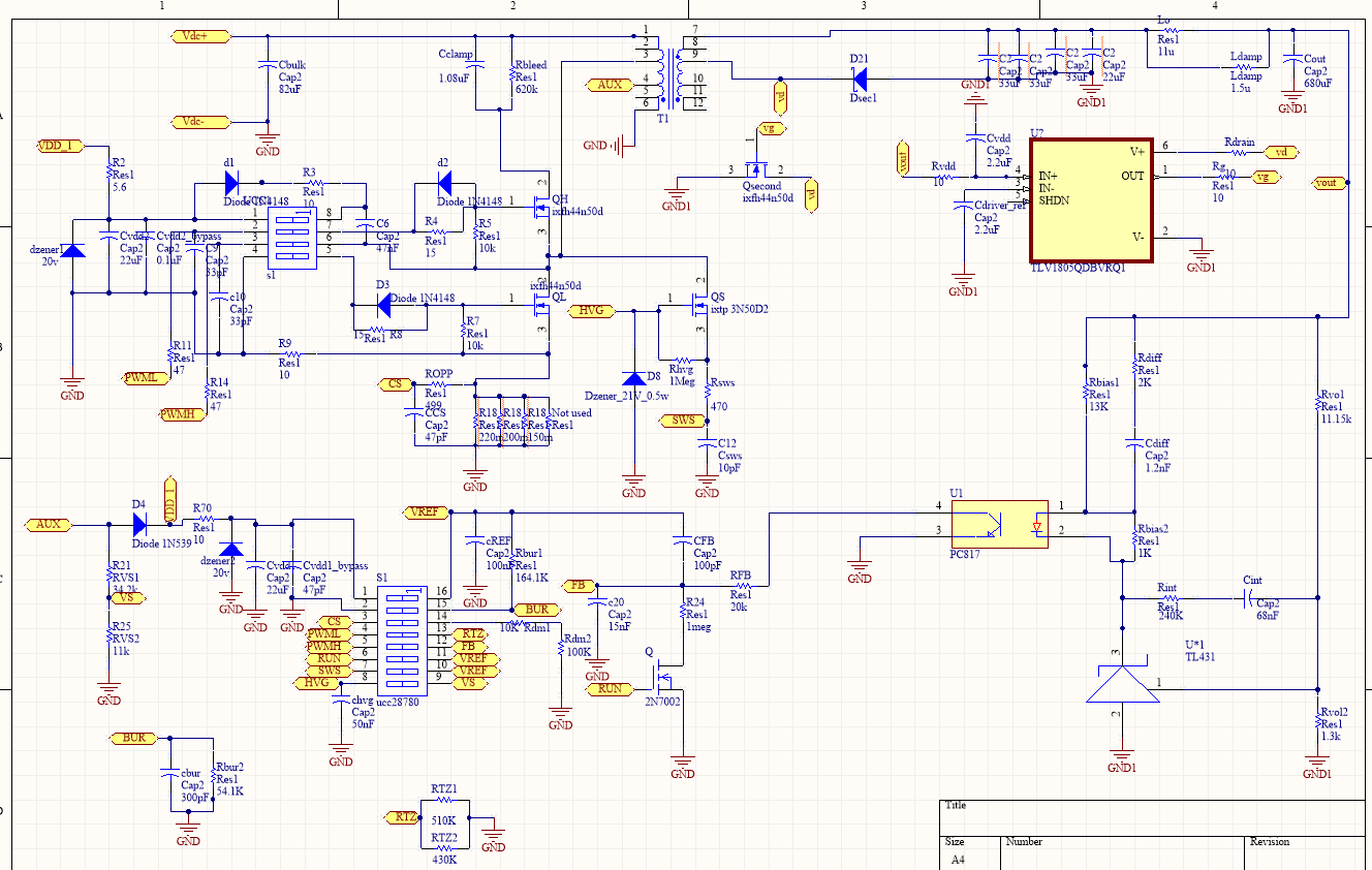
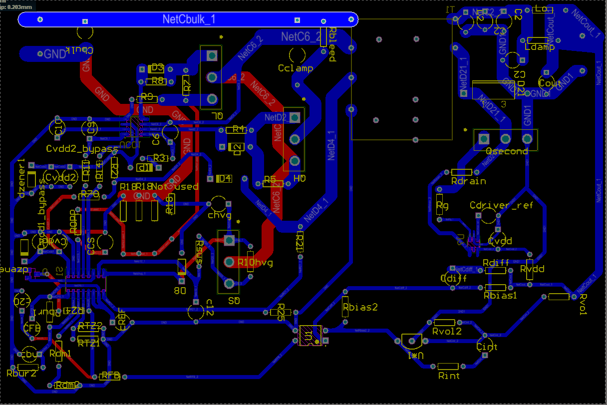
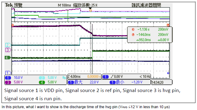
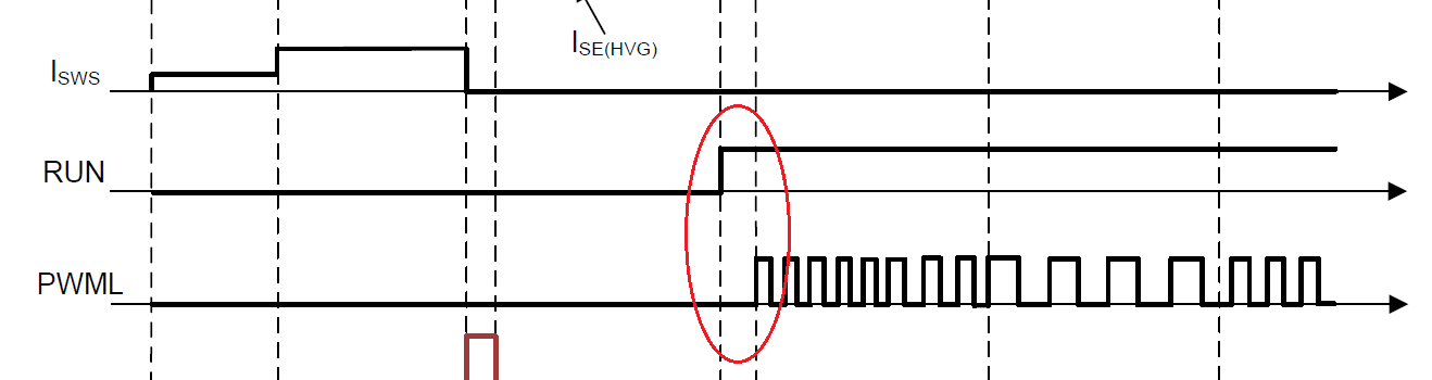
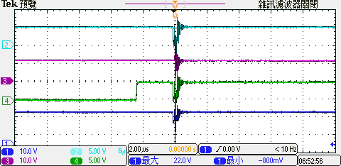
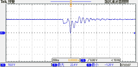
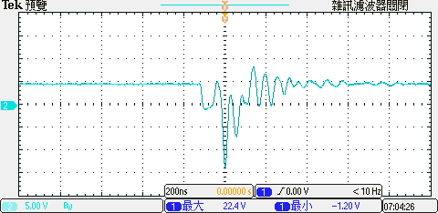
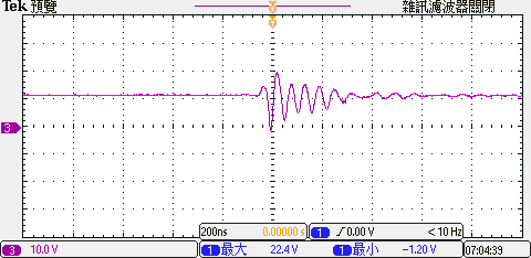
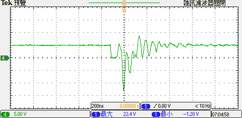
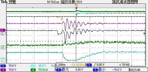
在word文件中,有我從示波器捕獲的波形。測試條件為輸入24v,電流限制為0.5A,當前VDD超過啟動閾值(17.5V),並且具有參考電壓(5V),有時為RUN PIN(5V)有信號,有時無信號,但始終沒有用於PWML的信號。QL和QH在使用組件時使用ixfh44n50p(N溝道增強模式,功率MOSFET),用於啟動+ zvs感應的mosfet使用ixtp 3n50d2(N溝道,耗盡模式MOSFET)。
我已經使用了ti提供的Excel來計算所有參數值。目前,它也是根據excel上的參數進行設計的,但實際電路行為也沒有pwml信號。我想問一下是否有任何參數需要更正。UCC28780-Excel-Design-Calculator-24v-2.xlsxTI ucc28780 issue.pdfLittelfuse_Discrete_MOSFETs_N-Channel_Depletion_Mode_IXT_3N50_Datasheet.PDF.PDFLittelfuse_Discrete_MOSFETs_N-Channel_HiPerFETs_IXF_44N50P_Datasheet.PDF.PDF

  • HI, There

    Your post is forwarded to expect, pls expect a response by Friday.

    Yunsheng

  • Hello,

    Basically , The PWML will following RUN signal after ~2.2us . if you see the RUN is go high , while there is no PWML . please check the soldering on the board . try to another IC and carefully check the soldering . make sure what your said PWML was captured on controller PWML pin rather than on low side MOSFET VGS , since the driver IC may can't transfer the signal to FET if it's at UVLO .

    Once VDD can ramp up to 17.5V , that means your start up circuits(BSS126) are good , don't need to adjust it.

    Also RDM and RTZ will not impact start-up , don't change them at beginning debug stage . just follow the calculator results .

    its's a good start that you can read the application note. almost all of start up issues are listed in it.

    Thanks.

  • Hello,

    I have confirmed all the solder joints and the polarity of the transformer are  all  correct. 

    The measurement point is the fourth pin of the ic, not the low side mosfet.

    My start up   circuits   is use ixtp 3n50d2.       If not using bss126 (rdson max is 700 ohms in bss126)Is it the key to the absence of pwml?

    Because all parameter design is calculated by excel,The main switch QL&QH uses IXTA3N50D2,Other parameters are the same as excel.

    Are there other possible reasons that my pwml has no signal?

    The following is the waveform I captured on the oscilloscope and my excel design.

      5187.UCC28780-Excel-Design-Calculator-24v-2.xlsx

  • Hello,

    The HV start FET will not influence PWML as long as the VDD can be charged to 17.5V and regardless you used  ixtp 3n50d2. or other depletion mode FET.

    The PWML will follow RUN signal after 2.2us , It will not impacted by external components setting ,since you already get the RUN pin go high.

    Could you please use multimeter to check the impedance of PWML vs GND to see if it shorted to GND , and try to replace the controller with a new one.

    See the power sequence of RUN and PWML in datasheet page 28.

  • Hello,

    I have used a multipoint meter to measure pwml to GND (pin4 to pin2) and found that the resistance is 0.43meg ohm during the measurement.

    The currently used ic ucc28780 is also new.

    Are there other possible reasons for the absence of PWML?

    The picture below is measure pwml to GND (pin4 to pin2)

  • Hello,

    The time scale you used for capturing PWML is 400ms/div , could you please use 2us/div to capture it ? and zoom in when VDD reach to 17.5V.

  • BTW : We recommend use 4 layers PCB for ACF application. looks like your board is signal layer . that is not good for PCB layout design.

  • This is what I took from the oscilloscope,source 1 is VDD pin, Signal source 2 is ref pin, Signal source 3 is hvg pin, Signal source 4 is run pin.

     The scale of one grid is 2us/div.

    Next, I will individually zoom in the signal sources 1~4 to see.

    The PWML will follow RUN signal after 2.2us,It can be seen from the oscilloscope that there is noise about 2.2us after the RUN pin signal becomes high.

    I don’t know what caused this,The ref pin has a bypass capacitor of 100nF, and also try to be closer to the IC ucc28780.

    Is there any other factor that may cause these shocks?

    Is this the reason why there is no signal in my pwml?

  • Hello,

    Because I am still a graduate student, most of the dip components are currently used in the laboratory.Considering the technology and components of the laboratory, the double-layer board may be the main choice.

  • Hello,

    The waveform shows controller already generated PWML when RUN go high 2.2us later .even you didn't captured the PWML signal.

    Please follow the application note to check what protection has been triggered. I recommend you to capture transformer primary winding current , low side FET VDS signals to identify what protection happens .

    Thanks.

  • Hello,

    The following is the signal I captured.

    source 1 is ref pin, Signal source 2 is low side FET VDS, Signal source 3 is hvg pin, Signal source 4 is transformer primary winding current .

    At this time Vin=25V, current limit is 0.5A, (design specifications are Vin=60V, Vo=24V, Po=100w).

    From this picture, you can see that the low side fet (Signal source 2)seems to be conducting (not sure).

    If there is conduction, is it one pulse?It is protection and then one pluse?

    The ref signal oscillates to negative 12V (after the first PWML signal is turned on), is this normal?I don’t see this action from the datasheet sequence diagram.

    Thanks

  • Hello,

    Firstly, I want to to say you have chosen improper topology for your application ,  60VDC IN and 24V/100W output . UCC28780 operates in transition mode . the low input voltage and high output voltage and power will let you get a low turn ratios of transformer . that means your transformer primary turns is also low . In order to decrease the core loss of transformer , you have to use a large Ae transformer . low input voltage and large Pout also means , the current stress when FET is turn off is very high .  for your application , I recommend you chose active clamp forward topology . the controller can be UCC2897A.

    If you want to study ACF controller , I recommend you firstly buy a EVM board or released product in the market to test. Frankly speaking, ucc28780 control strategy and ACF operation mode is a little difficult to understanding for a just graduated engineer , our support resource is limit. we don't have enough time to teach you hand by hand. anyway , we are always thanks for your interesting in TI's part . if you have specific question about ACF , please post it in another thread. we'll reply you.

    Thanks.