This thread has been locked.

If you have a related question, please click the "Ask a related question" button in the top right corner. The newly created question will be automatically linked to this question.

INA220: INA220 failing in first few weeks at alarming rate

Part Number: INA220

This enquiry is about INA220's failing at an alarming rate in the first few weeks of service.

I cannot change the forum.

1st Line support could not help. They asked a lot of questions and I provided all the answers and now they want me to start from scratch again. Luckily I saved some of the correspondence. Please refer to the attached and let me know if you have any further questions.

Thank you

Lukas.

TI support Transcript.docx

  • Hi Lukas,

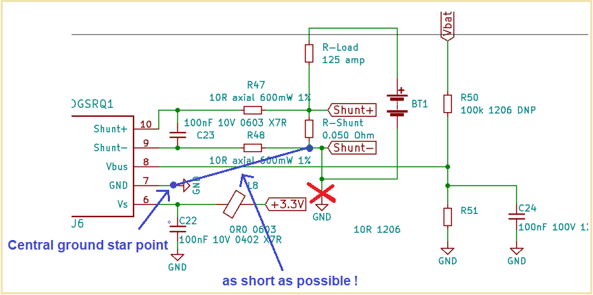
    I think you have a grounding issue. Due to improper ground connections of INA220, shunt and battery, voltage drops and inductive kickbacks will occur which force the inputs of INA220 to go well below -0.3V.

    These modfications should fix your issue:

    Kai

  • Hi Lukas,

    This does sound like over/under voltage type of failure, most likely under voltage given the configuration. If this is the case, good grounding should help and will reduce parasitic impedance, as Kai suggested.

    Besides, you may replace R47/48 with ferrite beads with larger DC resistance such as 50Ohm. This value is larger than normally recommended but it might be necessary to increase the robustness of the system. You might also add Schottky diodes as clamp, before R47/48 and after the shunt.

    Regards, Guang

  • Hi Kai,

    Thank you for your feedback. The above diagram was quickly altered during a live chat and may have projected the wrong impression. The objective of this diagram was to confirm polarities rather than connection lengths.

    Please refer to the diagram below, which is drafted with the power source and main loads to the left and the electronics to the right. You will see that the currents divide such that load currents are not close to the electronics. If you need more clarification on how currents are distributed in the system, I can focus on the looms, connector and PCB layout.

    Bear in mind that we experience INA220 failures on static batteries where the battery is switched on, with nothing connected to the output terminals.

    Also keep in mind that some batteries are built in a single box, where the shunt is within 20cm ( 6 or 7 inches) from the electronics and other batteries are built in multiple boxes where the shunt can be as far as 2 meters (roughly 2 yards) from the INA220. Failures appear across all types of battery box construction.

    Please let me know if you need more details.

    Thank you

    Lukas

  • Hi Lukas,

    your diagram didn't come through. Can you please post again by using the "Insert File" button (paperclip) in the header of textbox?

    Kai

  • Kai, the symbol I attached to the ground plane "GND" is just to label the ground plane. The power supplies on the PCB are fed from the battery positive and returned directly to the battery negative. The electronics and INA220 are fed from a buck converter to 5 volt and stepped down through a LDO to 3.3 volt. These return paths are through a substantial ground plane. Please do not confuse the position of the "GND" symbol with a current path position.

    Thanks

    Lukas

  • Hi Lukas,

    Thank you for the additional statements. I don’t see any obvious issue in the schematic or the illustration of the PCB. 

    You may want to probe the transient voltages on the input pins when switching the battery on/off

    Regards, Guang

  • Hi Lukas,

    I still think that there's a grounding issue. Unfortunately, your simplified schematic does not fully show what's going on in your application. I would need to see the whole PCB and the whole schematic.

    Kai