This thread has been locked.

If you have a related question, please click the "Ask a related question" button in the top right corner. The newly created question will be automatically linked to this question.

INA121: oscillations on using INA121

Part Number: INA121
Other Parts Discussed in Thread: INA103,

Hi Sir,

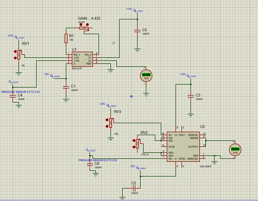
A customer has bought two in Amp: INA103 and INA121.

He'd like what is the difference between this two instrumentation amplifier.

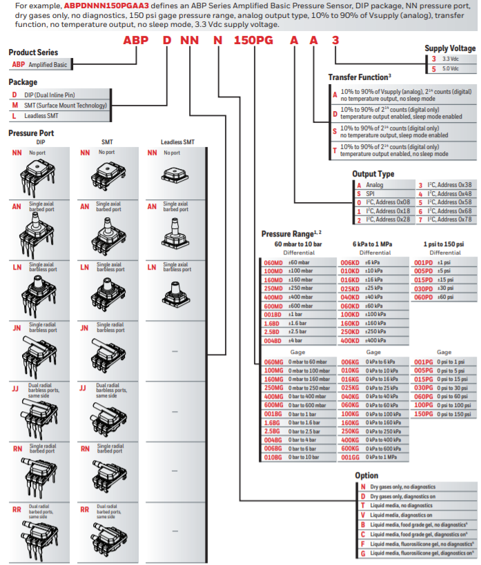
He used it to amplify the signal from a Honneywell sensor:

sensing.honeywell.com/honeywell-sensing-basic-board-mount-pressure-abp-series-datasheet-32305128-en.pdf

He obtained a gain of 4 .. However when he worked with the INA121, he got a lot of oscillations, but when he worked with the ina103, he had no problem.

Thank you for your valuable suggestions.

  • Hi Frank,

    What are the load of your INA121 and/or INA103? What kind of oscillation do you see, via simulation or actual sensor configuration? INA103 has high BW than INA121, but INA121 has much lower I_bias current than INA103. Would you show us the analog front end of wheatstone bridge in the pressure sensor (unless it is integrated pressure module)? 

    Please make sure that you have an analog input stage as suggested in Figure 3, where the INA121 has proper input bias current return path and input common-mode range. If you provide me with actual sensor parameters, I can simulate it for you. 

    Enclosed is the simulation in INA121. 

     /cfs-file/__key/communityserver-discussions-components-files/14/INA121-Gain4-02222021.TSC

    Best,

    Raymond

  • Hi Raymond,

    Thank you for your response.

    I am using the ABP Honeywell:

    The load of my InAmp is in PLC: 79.7K ohm... I'm don't doing a simulation, i'm using my pressure sensor. I have added a resistor 10K to V+ in as the figure 3 of datasheet of ina121..

    I have another problem, every time I get closer to the circuit, the oscillations increase.

  • Hi Frank,

    Q: I have another problem, every time I get closer to the circuit, the oscillations increase.

    Can you shorten the your input and output loose wires in the breadboard configuration? There are too many antenna (LC parasitics) around the output of INA121. In addition, the scope probe has capacitance, which it may cause the oscillatory effects. Here are my suggestions:

    1. shorten the loose wires around the INA121 

    2. Buffer INA121's output for this configuration.  

    If you see additional oscillation at the output of INA121, please let me know. 

    Best,

    Raymond

  • Hi Raymond,

    Thank you for your advice.

    I have followed the steps that you have recommended,

    During the short circuit I made on the ina121 inputs, I had no oscillations. However, I inform you that this circuit is going to be folded into a control board, at the bottom. In such a way I am using another ina121, with which I receive the current loop of the transmitter of a temperature sensor, I don't have much problems with it, but it also oscillates every time I get close to the circuit. However for the voltage output of the pressure sensor, the variation affects me a lot for my measurement, I am using long 18 AWG cables.
    Please Skip the file named ultimoyaaaa ...

    Thank you very much

  • Hi Frank,

    You told me that you are using ABP Honeywell. There are many models in the family. Can you provide me with the complete the part number? How sensitive is your pressure sensor's sensitivity? 

    I was wondering the oscillation you observed is real. If the sensor has a few psi in FS, you may create a pressure change when you walked over it. Can you place a piece of electrical tape over the pressure port and see if it still "oscillates" when walking close to the sensor? (my speculation). 

    I am unable to explain the issue currently, if you have placed a op amp buffer at the output of INA121.  

    Best,

    Raymond

  • Hi Frank,

    Please also try the following configurations. 

    1. Reduce C4/R2 from 100nf to 1nf (from your previous schematic).

    2. Remove Rg gain resistor and loose wires from pin1 and pin8, which INA121's Gain=1, if Rg is open, and see if the "oscillation" at the INA121's output still persists. 

    Please let us know if your issues are resolved. 

    Best,

    Raymond 

  • Hi Raymond,

    I appreciate all the support you are giving me. I'll be away for a few days, away from my project with the circuitry. But I have a query, I am doing this project as a university thesis. I would like to know if there is any way why I should use the INA103 and not the INA121 for the voltage measurement of the pressure sensor, considering that I am using shielded cable, and that I am also using the ina121 for the current measurement of the temperature transmitter (4 to 20mA). (which does not give me problems so far).

    I am using the abpdjjt001pgaa5 sensor with a range of 0 to 1 psi, in which I only intend to obtain measurements from 0 to 0.6 psi approximately.
    It is very unlikely that the pressure variation due to my presence is the cause of oscillation, since I am using the pressure sensor to measure the level of a tank. Just putting my arm close to the ina121 circuit, I am producing the oscillation.
    Maybe I have been using this term wrong, since I have a confusion with sensitivity and resolution, since this is 0.000702psi / mV, which expressed in level measurement would be 0.4mm / mV.

    The other tests will be done when I return home.

    Thanks.

  • Hi Frank,

    I do not think that INA121 is the issues. I noticed that abpdjjt001pgaa5 sensor may use nominal 5Vdc (or 3.3V) for excitation voltage and draw current up to 3.8mA (nominal is 2.7mA), which means the internal Wheatstone bridge has overall 5V/2.7mA = 1.852kOhm. 

    The 10kOhm you placed at the bottom of sensor may be limiting the transducer's required bias current. Please try the following configuration. 

    /cfs-file/__key/communityserver-discussions-components-files/14/INA121-Gain4-02262021.TSC

    Please let me know if this is the problem. 

    Best,

    Raymond

  • Hi Raymond,

    In the image that I attach in previous messages,

    it is observed that I am not using a 10K resistor followed by the pressure sensor,

    in fact I am not using any resistor for it in + IN V. -IN V uses a variable resistance set at 0.5V which is to eliminate the pressure sensor offset,

    since with a gauge pressure of 0psi, it is equal to 0.5V. Please can you text me what resistance you mean.

    Thanks.

  • Hi Frank,

    Can you send me the complete pressure sensor schematic of INA121? I am trying to solve your issue in "Just putting my arm close to the ina121 circuit, I am producing the oscillation." .  I am trying to figure out the "oscillation" issues are occurred from your pressure sensor configuration or in the INA121 sensing circuit. 

    Once we resolve the "oscillation" issue, we can work on the 0.5V offset issue at 0psi, 

    Did you try the following sensor configuration? Please let me know your finding. 

    Best,

    Raymond

  • Hi Frank,

    the sensor already contains an amplifier :-)

    There's no need to connect it to the INA103 or INA121. And please replace this 100nF at the output of sensor by a 1nF cap, as already mentioned by Raymond.

    Kai 

  • Hi kai,

    Thank you.

    I need the in amp for substract the 0.5V and amplifier aprox 4V/V for the analog input of PLC

  • Hi Frank,

    I would do it this way:

    frank_ina121.TSC

    Keep in mind that the 0.5V offset voltage generated by P1 is only as precise as the +12V supply voltage. So as an improvement you might want to use a voltage reference chip instead. Also take care that the supply voltages of INA121 are clean, stable and noise-free. If they contain any HF-ripple further supply voltage filtering might be needed.

    Kai