This thread has been locked.

If you have a related question, please click the "Ask a related question" button in the top right corner. The newly created question will be automatically linked to this question.

OPA2182: Noise of OPA2182 vs OPA2192

Part Number: OPA2182
Other Parts Discussed in Thread: OPA2192

Hi,

I have used OPA2192 in a difference OPAMP stage (shown in the attached picture, U78-A). Due to temperature drift concerns I have switched to the OPA2182.
Now I compared the noise flloor of those two variants as this is as well as important to us as temperature drift. Measured at J33 with an active voltage rail probe. Inputs of difference amplifier connected both to GND.
I can see two things:

1. Overall noise level of OPA2182 output is slightly higher than noise of OPA2192 output (ADC results show that OPA2182 shows a factor 1.15 higher noise floor) 
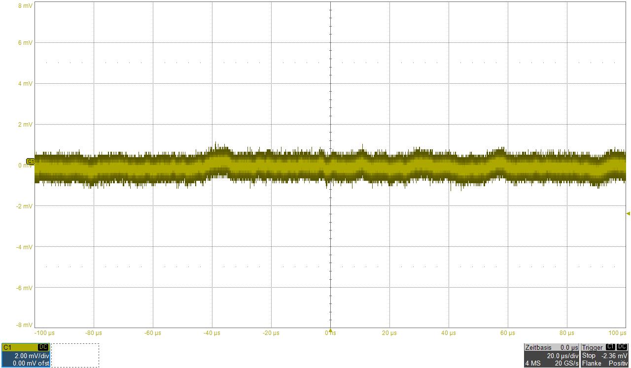
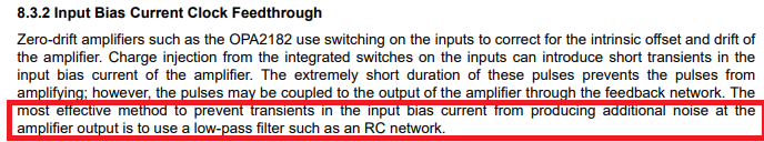
2. OPA2182 output shows short spikes (please see picture)

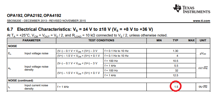
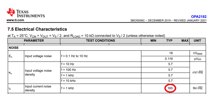
From the datasheet of those two devices OPA2182 should perform much better in the 1/f noise (low frequency) and should be about the same at noise with higher frequency.
Current noise of OPA2182 is much higher as OPA2192.

I assume that the short spikes come from the input current spikes of the chopper amplifier. I have studied the document "Intrinsic Noise Sources in Chopper Amplifiers" from John Caldwell, TI.
My calculations show that chopper noise should not be a concern because R526 and R525 are only 270Ohm.

Any ideas what can lead to those spikes?

Thanks and best regards,

Patrick

Schematic:


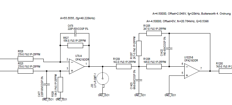
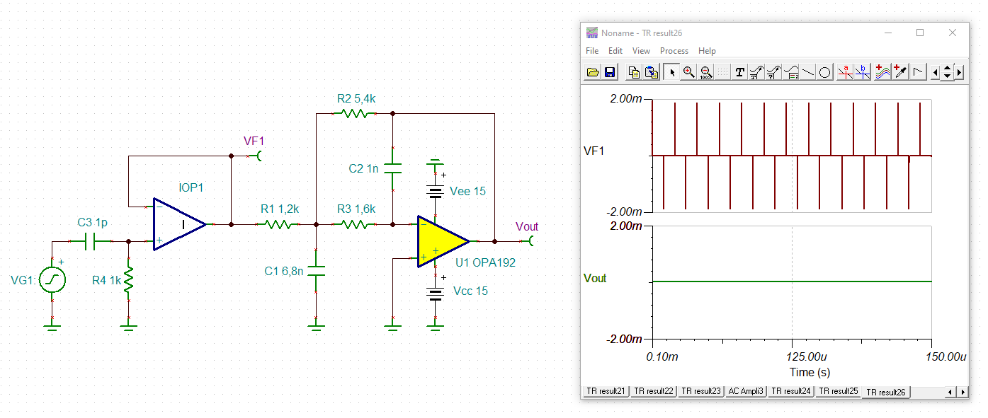
Output of OPA2182 @ U78-A:

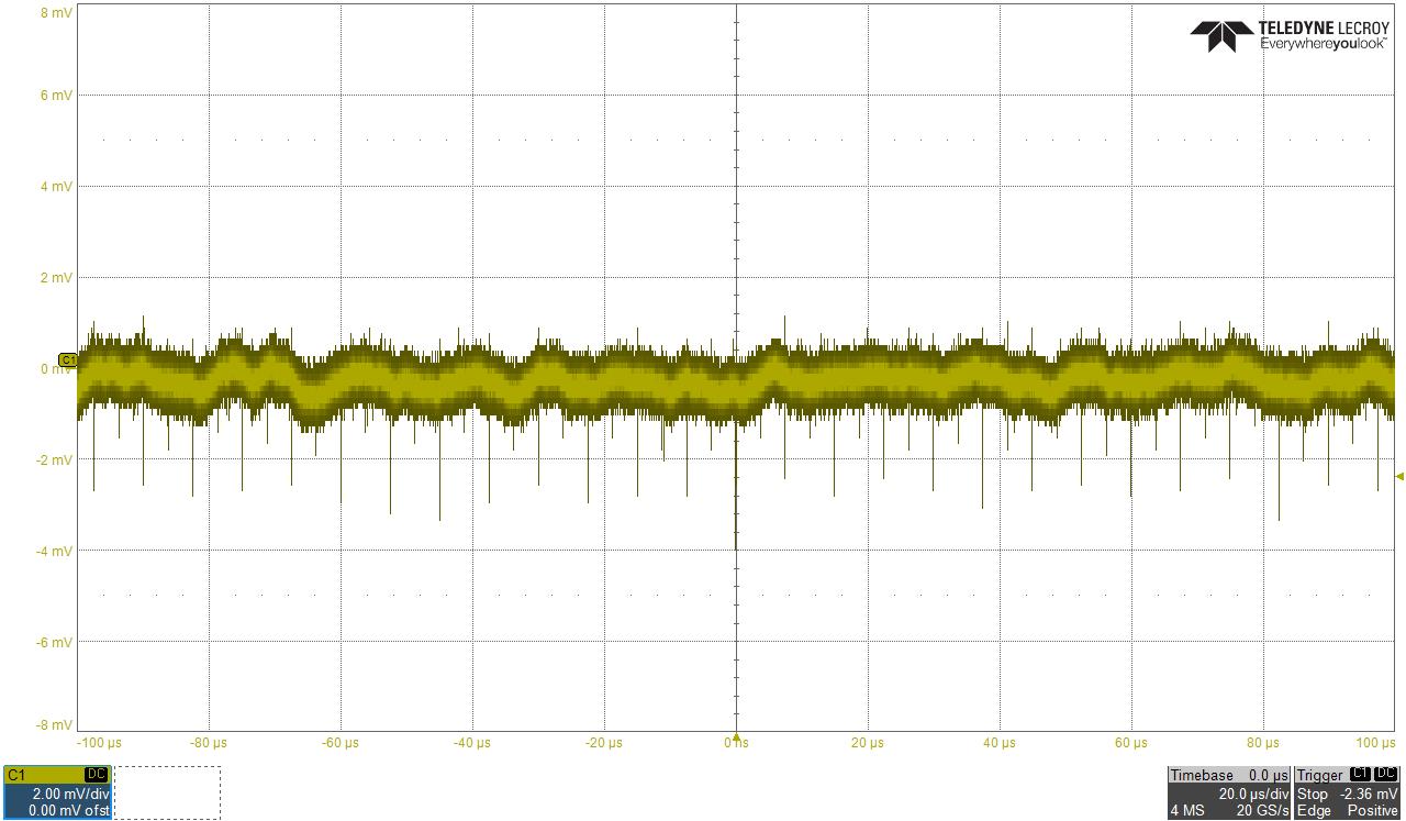
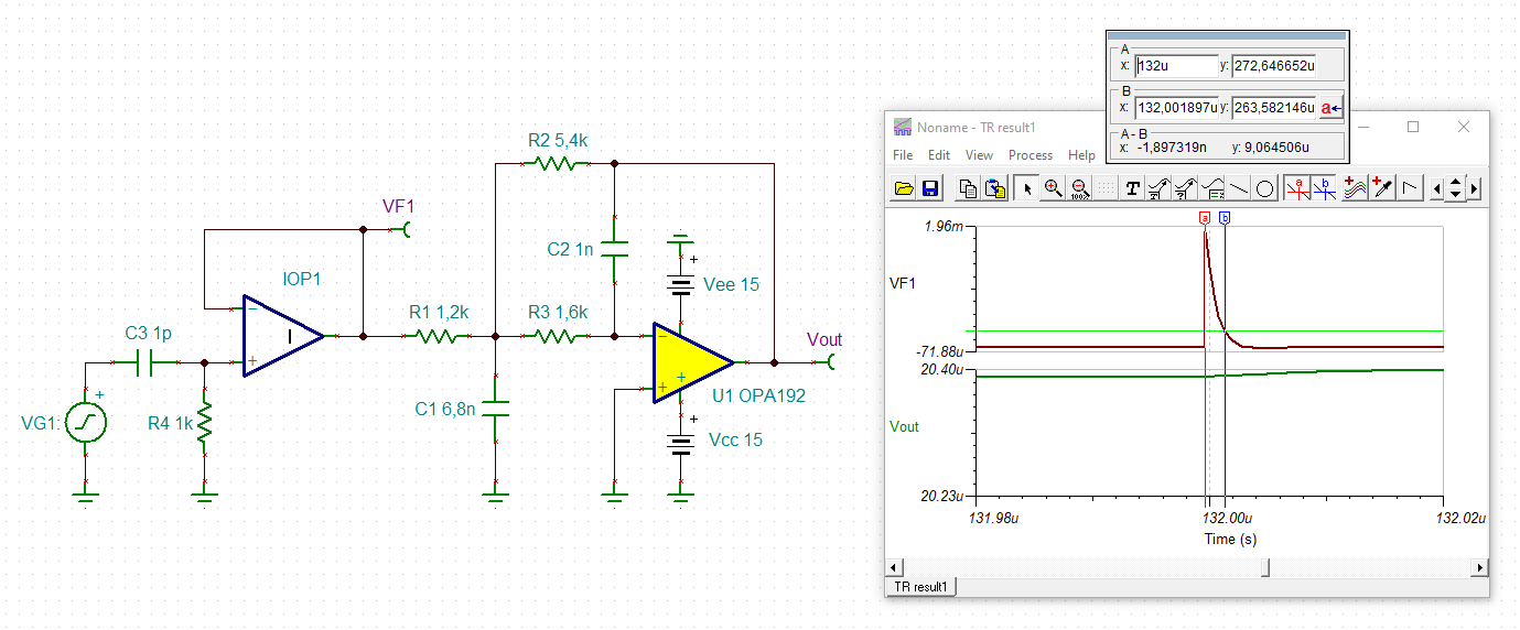
Output of OPA2192 @ U78-A:

  • This is correct.  OPA2182 1/f input voltage noise is better than OPA2192 because it is a chopper op amp with 1/f being cancelled.  However, the input current noise of OPA2182 is much higher than OPA2192 (see below), which gets converted across the input impedance, thus resulting in the voltage spikes at 250kHz chopping frequency of OPA2182. Because of few nano-second duration of the IB current spikes, their magnitude may be in 10uA range - thus the voltage spikes may reach 10uA*270ohm = 2.7mV and be fed into the output across the feedback capacitor, which acts like a buffer for sharp edges of the spikes.

    Therefore, the best to eliminate the voltage transients at the OPA2182 output is to use a low-pass filter at the output of the second-stage.

  • Hello Pruf,

    John Caldwell's information about Intrinsic Noises in Choppers is very informative. It was the first time I had viewed the information and it does cover the subject nicely.

    Your OPA2182 noise vs time plot clearly shows the periodic spikes indicative of the the commutative switching that occurs in the frontend of a chopper op amp. John clearly illustrates in slide 21 how the chopper current noise contributes to the op amp's output noise.

    Indeed your circuit uses low, 270 Ohm input resistors in the OPA2182 difference amplifier stage, and they do shunt the high-value 15 kilohm feedback resistors. The equivalent resistance is indeed low, but nevertheless there is still transformation of the small current spikes into input voltage spikes and they will be present. And as seen in John's slide the load presented to the op amp's output affects the spike level at that point.

    We have observed that when a chopper op amp is placed in a difference amplifier configuration that the current spike issue becomes more pronounced. It is related to the fact that the equivalent impedance each input of the chopper op amp sees is not perfectly matched despite accurate resistors being used. It is not only the resistances, but the capacitances that need to be balanced and that is not easy to achieve with all circuit layouts. Roughly stated, the more impedance imbalance had between the two inputs the more exaggerated the current spike tends to be.

    Additionally, you mention that the noise image was measured at J33, the difference amplifier output. It would be interesting to know if U1205-B's input circuit is disconnected from J33 if the transient levels change. Removing R1208 might be a way to do that as long as U1205-B remains stable.

    Regards, Thomas

    Precision Amplifiers Applications Engineering

  • Also Pruf, while Tom and Marek have answered the chopper noise issue, I tried running a lower noise MFB RC solution for you 2nd stage, The values are little hard to read, but I think this is your current solution where the solutions at the bottom are ideal, you are not quite getting the target Fo and Q, but close,of  the min GBP of 1.18MHz is solving for a min loop gain of 20dB. 

    If I run an output total noise sim for your values, and the slightly improved values shown below, there is a slight lowering in this MFB output noise - your first stage is dominating of course, so this will make little difference, but just checking and passing on in case you want to try these RC for your stated target filter, the lower noise curve are the improved RC values. 

  • Hi Pruf,

    C1423 should be able to absorb a lot of the pulses coming from the output of OPA2182:

    pruf_opa2192.TSC

    The pulse duration is assumed to be about 2ns:

    Kai

  • Hi,

    To all contributor: thanks for the support and the valuable feedback.

    If the current spikes are in the range of 10uA than it all makes sense and it is clear to have spikes in the range of 2...3mV at the output of U78-A.
    Next I will try to isolate U78-A from the next stage to see the impact the 2nd stage has to those spikes. I will also try to remove C478 and C477.
    Just to see if this has an impact as well. Although I have seen that those capacitors improve on extrinsic noise.
    Most of those spikes gets filtered out by the next stages but good quality measurement is a bit tricky on the target. The result is best seen on the ADC raw values. 

    I will get back as soon as I have more results...

    Best regards,

    Patrick

  • Hi Pruf,

    can you say what the soure of your circuit is? Can you add it to your schematic? I ask because C477 and C478 might be needed for stability and noise suppression.

    Also, do not directly touch the output of U78-A with the scope probe but insert a 100R isolation resistor.

    Kai

  • Hi Kai,

    The source is a 60mV shunt (but only 1/10 of its range is used for this measurement, nominal input is +/-6mV).

    The first stage is stable without the capacitors but they do suppress quite a lot of extrinsic noise.
    Also by limiting the bandwith of this first stage there is an improvement of the total noise level of the first stage output.

    Regards,

    Patrick

  • Hi,

    I did build the first stage on a TI DIYAMP-SOIC board and I have made a measurement with and without C478/C477.

    It shows that those capacitors give an overall improvement on the noise floor (approx. 20% less noise amplitude) but on the other hand doubles the amplitude of the chopper spike at the output.
    I did the measurement with a 1:1 coax cable ditrectly from the DIYAMP-SOIC board to the oscilloscope (no isolation resistor). No additional load at the OPAMP output.

    So with next measurements I will try to figure out what impact an additional load will have on those chopper spikes...

    Regards,

    Patrick