This thread has been locked.

If you have a related question, please click the "Ask a related question" button in the top right corner. The newly created question will be automatically linked to this question.

XTR101 Rs

Other Parts Discussed in Thread: XTR101, XTR105, XTR112

Hello,

while using a resistor to set Rs the XTR101 acts correctly.

Into an ATE as I am using a Pickering 40-297 PXI card (Resistor card) in order to change multiple Rs values the XTR101 does not works correctly.anymore.


Is there any relation between a 'moving' Rs value versus a fixed one that can generate the wrong behaveiour?


I can confirm the Pickering card works correctly since each time I set a fixed res value and measure it , I measure the expected value (UUT disconnected).


Thanks,Giuseppe


  • Hi Giuseppe,

    Could you describe the behavior you are seeing when the XTR101 does not work correctly? A simple schematic of your system may also help us with the de-bugging process. One possibility is that the connection between your PXI card and the XTR101 is creating a large loop area that is introducing noise into the XTR101. Also, as I am unfamiliar with how this particular PXI card operates, are you sure that the resistor values are floating? It would be good to verify that neither terminal of the resistor being switched-in is grounded.

  • Hello John,

    thanks for your reply.


    The Pickering card (attached the manual) set different res values in order to find the correct one (board calibration).

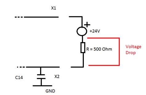
    The correct one is the one that allows a specific voltage drop over a serial 500Ohm res:see X1/X2 .


    I would exclude the large loop area  since the card does not  add  too much path.

    The onnly proble I can think of is while the card move from resvalu1 to resvalue2 somehow, due to the relay reaction time,

    it can induce open.


    Any betterr idea?


    Thanks,

    Giuseppe


    5417.1126.SCANS_54000.REN_54000B6521036-00_B.PDF0028.40-297M.pdf

  • Addendum to my previous post.


    What if the Rs change values with no power cycle in between?


    Thanks,
    Giuseppe

  • Giuseppe,

    Would you please describe what exactly the part is doing when it is acting incorrectly? For example, is the output oscillating or does it remain at a DC value? Are you only seeing incorrect behavior when switching gains or during normal operation? This information is necessary for me to determine what is causing the part to malfunction.

  • Hello,


    Essentially it is an amplifier system that senses a voltage drop on a
    PT100 sensor and then translates this to a current which is sent along the
    wires to the receiving end. The current creates a voltage drop in the 500Ohm
    resistor, the voltages tabulated correspond to the current, if 10V is created
    then 20mA is flowing. The components are adjusted to get the required span of
    currents at different temperatures.

     Power for the amplifier is provided by the 24V supply (pin 8 of the IC
    XTR101 via a diode), the negative voltage is the voltage appearing on the
    500Ohm resistor plus any additional voltage drop down the wire.


    The Pickering 40-297 is being used to set the span between pins 5 and 6 of the XTR101
     
    As yuo can see the app is prettty straightforward: customer has to mesaure the voltage drop over a 500Ohm res onto X1 and X2 ((see UUT attached pdf and the following sketch)
     
    Problem is he gets different Rs values using a real Resistor as Rs vs the Pickering card set Rs values.

    The Pickering card stays inside a NI chasiss that has been earthed.

    The 24V is out of a isolated AC/DC.


    There is a 10mV drop from the Pickering card FP_GND (Chassis GND) and the UUT GND which makes me suspect the whoel problem is related to a wrong GND setup.

    I hope it make more sense now.


    Thanks,

    Giuseppe

  • Hello let me add the voltage measurement over  RES 500Ohm at different temperature.

    Measurement have been first done with a real RES and later with the Pickering Card(40-297-003).

    Pickering assure the CARD RES is floating.

    FP_GND is the Pickering card (PXI chassis) GND.

    InvertinG terminals means: inverting the card res terminals.


    I hope this helps understand the situation.


    Thanks,

    Giuseppe


    REAL RESISTOR

    Temperature

    Declared Value

    Measured Value

    T -40°

    T +30°

    T +60°

    30,9K

    31,1K

    1,98V

    7,58V

    9,93V

    9,9K

    9,96K

    1,98V

    7,61V

    9,98V

    47,K

    47,1K

    1,98V

    7,57V

    9,92V

    40-297-003

    40-297-003

    FP_GND tied to  X2 (See UUT Schematic)

    INVERTING TERMINALS - FP_GND tied to  X2 (See UUT Schematic)

    Temperature

    Temperature

    Set
      Value

    Measured Value

    T -40°

    T +30°

    T +60°

    Set
      Value

    Measured Value

    T -40°

    T +30°

    T +60°

    31,1K

    31,1K

    1,98V

    7,58V

    9,93V

    31,1K

    31,1K

    2,03V

    7,66V

    10,01V

    9,96K

    9,96K

    1,98V

    7,61V

    9,98V

    47,1K

    47,1K

    1,98V

    7,57V

    9,92V

    40-297-003

    40-297-003

    FP_GND FLOATING

    INVERTING TERMINALS -FP_GND FLOATING

    Temperature

    Temperature

    Set
      Value

    Measured Value

    T -40°

    T +30°

    T +60°

    Set
      Value

    Measured Value

    T -40°

    T +30°

    T +60°

    31,1K

    31,1K

    1,67V

    7,33V

    9,7V

    31,1K

    31,1K

    2,52V

    8,24V

    10,61V

  • Hi Guiseppe,

    I agree, this seems like it's likely a grounding issue.  Looking at the data, it looks like the cases where "FP_GND_Floating" are returning the same values that were obtained with the real resistors.  Is this correct? 

    Can the system not be operated with this FP GND signal floating? 

    Also, I'm a little unclear about something.  You've mentioned that this is a PT100 application, and most 2-wire transmitters are used in remote locations.  So, are you simply trying to test out the module with this "Pickering" card or is this part of the final application?  If so, can you explain the final application a little bit?

    Finally, the XTR101 is an older product.  The XTR105, XTR112, and XTR114 are all newer parts that are specifically designed for 4-20mA applications with RTD sensor inputs.  You may want to see if your customer has looked into those products. 

    Thanks,
    Collin Wells
    Precision Linear Applications