


Other Parts Discussed in Thread: OP07, TL074
Hi,
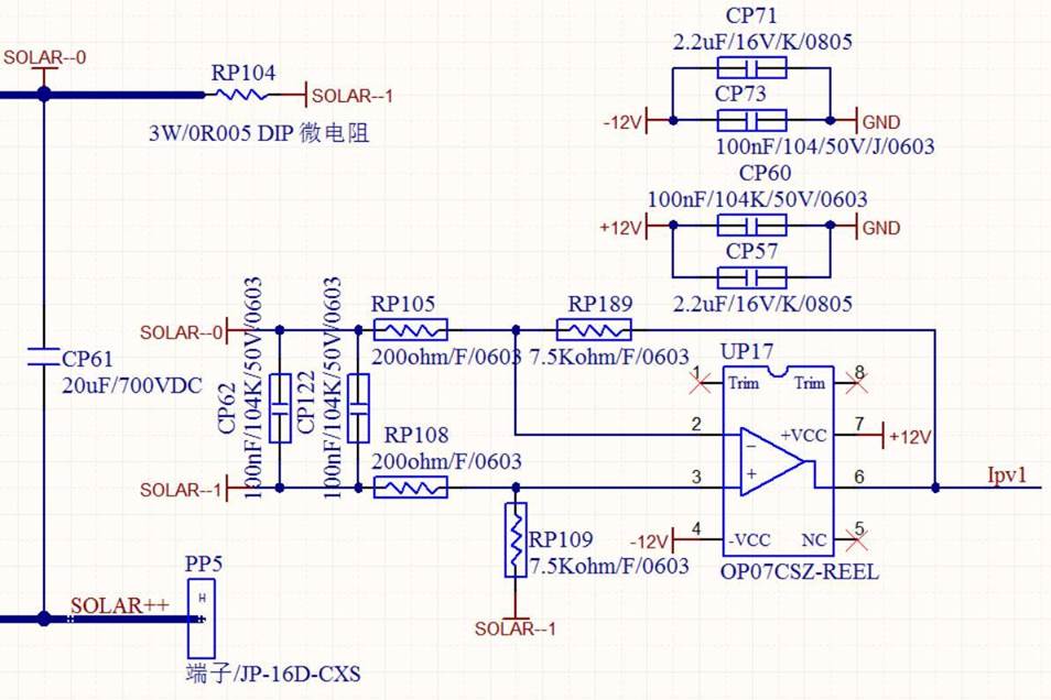
one of my customer is testing TLV07 to measure the DC bus current in their solar inverter system.
The schematic is as below, the shunt resistor is at the GND side, so the common mode voltage is almost zero. The current is DC, and there will be 20k ripple since an inverter of 20k switching frequency is connected to the DC BUS.
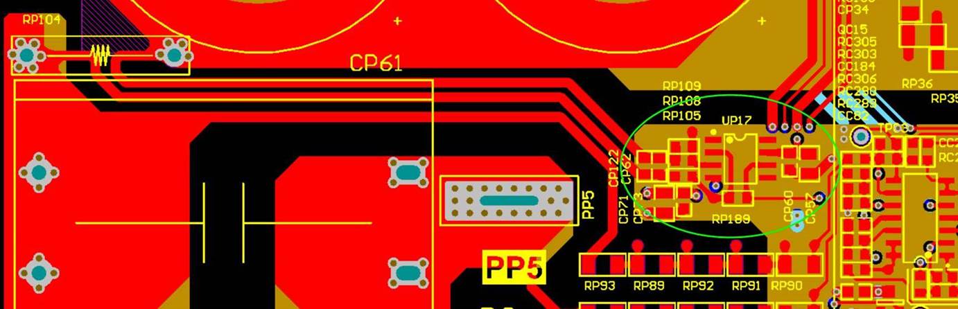
The layout is as below:
They test OP07 and TLV07 at the same circumstance with the same board, the test result is as below:
| POWER | current measured by OP07(A) | current measured by power analyzer(A) | error percentage(%) |
| 5% | 0.58 | 0.71 | -18.3 |
| 10% | 1.29 | 1.40 | -7.85 |
| 15% | 2.00 | 2.08 | -3.85 |
| 25% | 3.34 | 3.40 | -1.76 |
| 50% | 6.60 | 6.61 | -0.15 |
| 75% | 9.88 | 9.88 | 0 |
| 100% | 12.81 | 12.79 | 0.15 |
| POWER | current measured by TLV07(A) | current measured by power analyzer(A) | error percentage(%) |
| 5% | 0.47 | 0.68 | -30.88 |
| 10% | 1.07 | 1.38 | -22.46 |
| 15% | 1.79 | 2.06 | -13.11 |
| 25% | 3.19 | 3.39 | -5.9 |
| 50% | 6.71 | 6.71 | 0 |
| 75% | 10.30 | 10.09 | 2.08 |
| 100% | 12.83 | 12.44 | 3.14 |
Can anyone give me some suggestions how to improve the behavior or TLV07 to compete against OP07? Thanks.
