This thread has been locked.

If you have a related question, please click the "Ask a related question" button in the top right corner. The newly created question will be automatically linked to this question.

INA240: INA240-SEP, PWM rejection in Output

Part Number: INA240

Dear Team

I was designing a circuit with INA240-SEP.

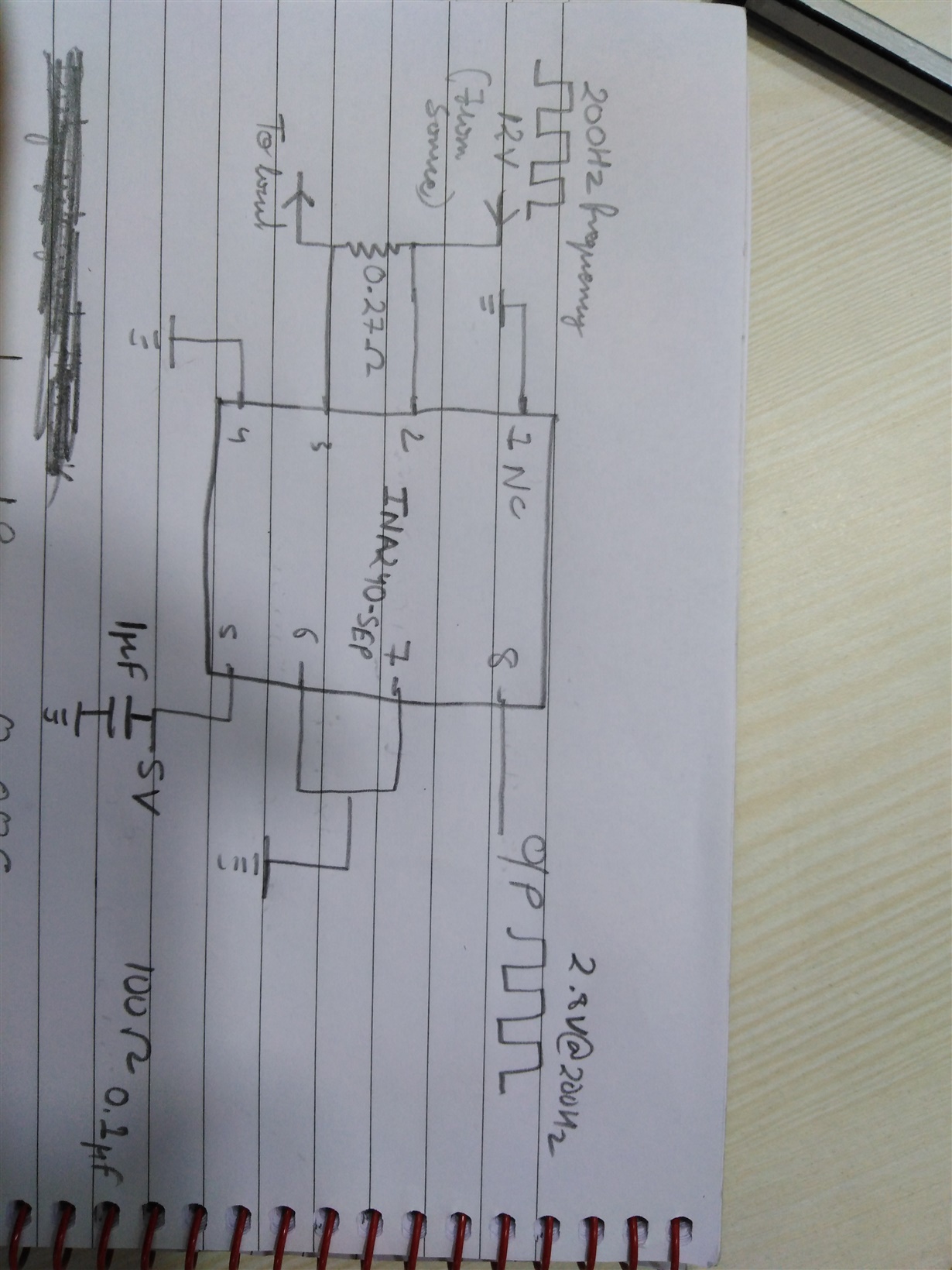
However, I am facing a problem in the output pin of this IC. I am applying a modulated signal (12V to 0V) @ 200 Hz at the input pins and am using a 0.27 ohm shunt resistor. Now, in the output pin I am able to get a voltage signal that is directly proportional to the current consumed, however, this output is also modulated at the same duty cycle in which I have applied the signal. Moreover, I am getting spikes as well.

The datasheet of the IC mentions that it has good PWM rejection, but it isn’t doing so. Attached is my circuit diagram.

I seek your support, an early response from your side will be highly appreciable.


I thank you in anticipation and look forward to hearing from you.

  • Hi Mayank,

    Please show the differential input to INA240.

    The INA240 rejects common mode PWM voltages, not differential. From your drawing, it appears the differential input is a PWM signal, which will of course appear at the INA240 output.

    If you want to observe the PWM rejection effect, you should remove the load, and short the 0.27Ohm. You'll see only spikes corresponding to the PWM transitions, and they should disappear quickly within a few uS.

    Regards, Guang

  • Thanks for the reply Guang

    Considering my case, is there a way to make the output a steady dc signal, given the differential input is PWM signal?
    Or is there any I C ir filtering circuit I can use to convert the PWM output voltage to a steady dc voltage?

    Regards
    Mayank
  • Hi Mayank,

    I'm a bit confused. Can you tell more about your application? Why are you applying a modulated signal to the inputs? What role plays the 0.27R shunt? What is your load? Why do you expcect a steady DC output signal?

    Kai
  • Hi Mayank,

    I have the same questions as Kai. Your goal for the circuit is fairly unusual.

    Anyway, can you do the averaging in digital domain? It should be fairly easy with such low frequency once the output is digitized.

    Regards, Guang

  • Hi Kai,
    My load is a LED traffic light, to control its brightness I am applying a modulated signal of varying duty cycle at its power pins. Now in order take feedback of its working status I am measuring the current with the help of INA240-SEP. Now, I have to give feedback, i.e., the output of the opamp to GPIO pin of my controller, and because it is GPIO i need a steady dc voltage.
    I hope this makes it clear.
  • Hi Mayank,

    in any case you would need an ADC input of microcontroller? Then you could do all the maths in your software, like Guang already mentioned. Or, you can add a simple RC low pass filter to the output of INA240 and generate the average voltage of the pulse train. A simple OPAmp unity gain follower could drive the ADC input then.

    Kai
  • Hi Mayank,

    It is an interesting proposition, however I think something is missing with you plan. Put the INA240 output to a GPIO will at best work poorly. The INA240 output is an analog signal. And it makes a lousy digital input signal.

    It is possible that you can use the INA240 output for the purpose of over current protection. If that is the case, you might be able to smooth it to a certain degree with RC output filter as Kai suggested. But you’ll probably want a comparator with hysteresis to buffer it before passing to the GPIO.

    Regards, Guang

  • Hi Mayank,

    It's been several days since your last post, so hopefully your issue has been resolved. I will close the thread for now. If you need more help, please reply to re-open the thread or ask a new question in a new thread.

    Best regards,

    Ian Williams
    Applications Manager
    Current & Magnetic Sensing