This thread has been locked.

If you have a related question, please click the "Ask a related question" button in the top right corner. The newly created question will be automatically linked to this question.

LM339: Hysteresis with two varying input voltages

Part Number: LM339
Other Parts Discussed in Thread: TL074, LM2903, TL072, LM311, LM319-N

Hi everybody!

I'm trying to find out how to enlarge the built-in hysteresis voltage of LM339 when comparing two different varying (AC) voltages at + and - inputs.

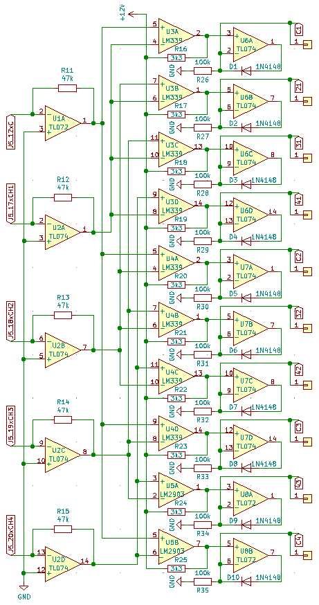
In my design i have 5 different AC signals which can vary from -10V up to +10V, and I wish to compare each signal with every other signal.

I take the signal from inverting buffer op amp (TL072 and TL074) and then send the conditioned signal to LM339 (and LM2903) comparators. After the comparator stage, each signal goes to the half-wave rectifier (TL074), and later on to the digital CMOS (CDxxx) stage. The rectifying stage is used to secure that the negative comparator output voltage doesn't go to the CMOS digital logic.

Power supply is -12V and +12V for each chip (TL072, TL074, LM339, LM2903). There is a bit of high frequency noise in each signal, and my plan is to filter that with simple RC filter..

When the input signals are close one to another I get the oscillation on comparator output, so I wonder is there a chance to enlarge the hysteresis? I need the hysteresis voltage (comparator precision) of about 0,1V. The problem is that the input signals are constantly changing (+/- 10V ampliude) so I can't use the design, or the calculator described in TI Kay/Claycomb article on hysteresis.

Also, I can't find out what is the maximum factory hysteresis voltage of LM339?

Thanks!

  • Hello Hrvoje,

    The LM339/393 family does not have any built-in hysteresis. Any hysteresis needs to be added externally.

    Instead of using the output half-wave op-amps, if you are just use a "split" pull-up resistor to level shift  the output, you can make the tap voltage near 0V.

    So if the supply is +12V and -12V, then use a split 10k and 10k pullup resistor. When the output is high, the tap will be at +12V. When the output is low, the tap will be at half supply, or near 0V. You can adjust the tap voltage if needed. That would eliminate stability issues with the op-amps.

    You can still add positive feedback. The output of the op-amps are a low impedance point, so adding feedback to the positive input is possible.

    See the non-inverting hysteresis appnote:

     http://www.ti.com/lit/an/sboa313a/sboa313a.pdf

    BTW: The LM311 (single) and LM319-N (dual) are specifically designed for split supply applications with a "floating" ground referenced open collector logic output, so you would only need a pull-up resistor to your logic voltage.

    And aslo watch the input range and output swing of the TL074 op-amps. The typical positive input limit is 3V above V-, so the lowest input votlage is -9V. Max is 4V from the rails (or ±8V).

  • Hrvoje,

    Since there has not been any response to this thread in a while, I will be closing it.  If you need any additional support, please open a new thread.

    Thanks

    Chuck