Other Parts Discussed in Thread: OPA313, TINA-TI, OPA325
I have a few questions concerning the configuration of the op amp in this application as well questions surrounding the choice of op amp.
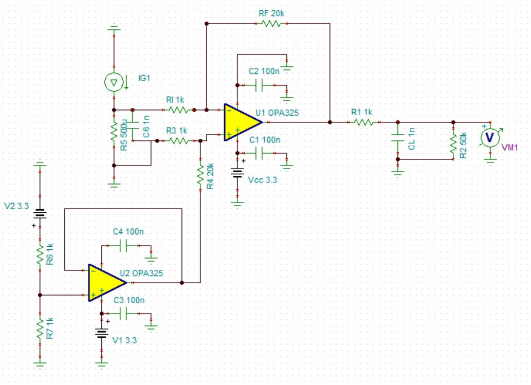
1. Would there be consequences of swapping the inputs to U1? (positive input to ground side of the sense resistor and negative input to high side of resistor)
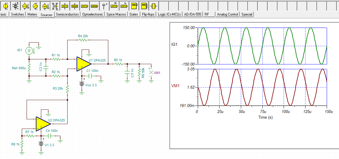
2. How does one go about choosing an op amp with proper bandwidth, slew rate, ect for this application? Say for low-side bidirectional current sensing in a motor control application where one wants to use an op amp for cost purposes.