This thread has been locked.

If you have a related question, please click the "Ask a related question" button in the top right corner. The newly created question will be automatically linked to this question.

INA190-Q1: Output voltage drop discussion

Part Number: INA190-Q1
Other Parts Discussed in Thread: INA190, OPA2365

Hi team,

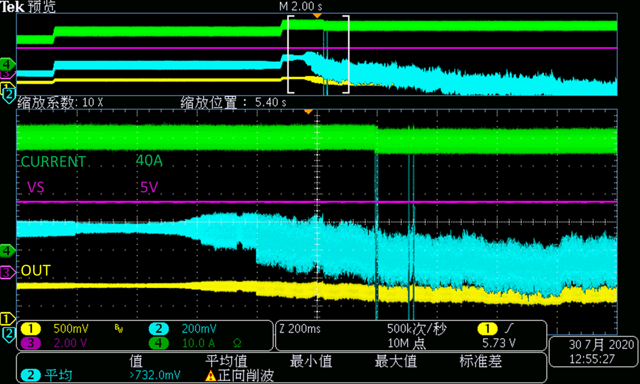
It is nice to know you here. My customer used INA190 as below, we saw OUT signal drop when we increase input current to 40A, could you please help analyze what may cause this signal drop? Thanks.

BR,

Charles Lin

  • Hey Charles,

    Could you specify the following:

    • The INA190 gain variant used?
    • The output load?
    • The blue waveform in oscilloscope image?
    • The load being measured?
    • The AC and frequency components of the load current (zoom in on the green waveform).

    It's possible they may need to drop the -3dB frequency of input filter or stabilize whatever output load they are driving. Not sure yet.

    Best,

    Peter

  • Hi Peter,

    Thank you for your help here. Please see my inputs below,

    1.INA190A3 is used here, gain=100;

    2.The output load is 40A to 70A. 

    3.The customer has second amplifier circuit, gain is 2, the blue one is the sencond stage output.

    4.The load in the waveform is about 40A.

    5.The load is DC load, no frequecny data here.

    What is -3dB frequency of input filter you recommend here? Any other solutions here? Thanks.

    BR,

    CL

  • Hi Lin,

    what is connected to the output of INA190?

    You said the 40A load current is DC. But why is the 40A load current so noisy? How did you measure the 40A load current?

    Kai

  • Hi Kai,

    INA190 connects to OPA2365.

    The noise may cause by the Oscilloscope. I double confirm this with the customer, they use DC Electronic load. Would appreciate it if you can share some professional suggestions here. Thanks.

    BR,

    CL

  • Hey Charles,

    I specifically need to know what the INA190 OUT pin is connected to? Is there some capacitive load before the OPA2365 input? A schematic is most useful here. It's possible the INA190 is not stable because it's driving a load that is too capacitive.

    A more zoomed-in scope shot could help reveal what AC components are coupling into the system and prove that the input filter -3dB cutoff may not be enough.

    If customer does not care about BW of measurement, then I would increase Cf to highest possible value and also increase RF up to 1kΩ.

    But first I would start trying to simplify the circuit and begin removing variables one by one to determine root cause. So I would test the following in order:

    1. Does the abnormal behavior only occur at 70A load? Try powering up to 70A directly and see if error occurs.

    2. Does the abnormal behavior go away when the load is dropped from 70A to 40A?

    3. Is the ground of the 70A load the same as the ground of the INA190? Are all grounds tied together?

    4. Remove the OPA2365 from output of INA190 and re-test.

    5. Remove any capacitor from INA190 output and re-test.

    6. Increase input filter values as I described above.

    Sincerely,

    Peter