This thread has been locked.

If you have a related question, please click the "Ask a related question" button in the top right corner. The newly created question will be automatically linked to this question.

INA168: 250A current sensor

Part Number: INA168

Hi Guys,

Greetings! Our customer need your help to check their circuit issue. 

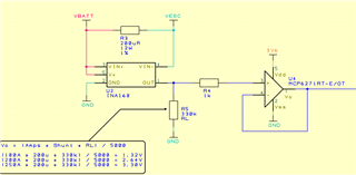
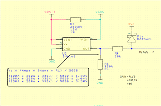
The circuit, at "no current thru shunt" gives an output of 141mV. This, if they have done their calculations correctly, they expect to see a 10.72A.

If they add a load so the shunt current is 500mA, the output raises to 148mV. This is what they expect to see for 11.1A shunt current, so there's an offset.

Why is the part outputting an offset of 141mV ? The output is connected to a Micro-Controller ADC input, with a clamp diode to protect against over-voltage on the ADC input.

Attached schematic:  it's a 250A current sensor.

Looking forward to your response. Thanks in advance. 

Best regards,

Jonathan

  • Hello Johnathan,

    The INA168 is current out so please make sure there is no other load connected at the output.  What type of ADC is it and what is the sampling rate?  This could also change the voltage at the output.  Also the input offset at room temp could account for only 66mV at the output.  To debug this and confirm it, I would remove R4 and measure with a high impedance meter at the output of the device.

    Gain is not far off since the delta from 0A to 500mA is not far off.  Please note the error on the Rshunt and RL will most likely dominate this error.

  • Hi Javier,

    Thank you for the response. I am still waiting for the customer's feedback.

    Best regards,

    Jonathan

  • Hi Javier, 

    Sorry for the delayed feedback. Here is the latest update from our customer. 

    With R4 removed they have measured a 4mV at no load and 11.6mV at 500mA, which they believe is correct and expected.

    The output is fed into a STM32G030J6M6 processor, the ADC external input impedance is 50kΩ.

    Regards,

    Jonathan

  • Hello Jonathan,

    So this is some loading issue they are having and please be aware there is something pulling it up when they connect.  There could be a load to a higher voltage.  Since the INA168 only drives current and with multiple paths the output voltage could vary depending on all the loads attached to the node.  The recommendation would be to add a buffer to deal with these additional loads.  There are benefits with using these current out devices and one is the bandwidth please let me know if you need further assistance.

  • Hi Jonathan,

    take care, the leakage current of BAT54 is about 100nA at room temperature. 100nA times 330k + 30k gives 36mV offset voltage Scream

    Also, the maximum source impedance the STM32 allows is 50k. Read page 67...69 of according datasheet. But your source impedance is 360k! So, as already recommended by Javier, I would add a buffer.

    Kai

  • Hi Kai/Javier,

    Sorry for the delayed response. Our customer have reworked with a buffer. The 1k resistor is to prevent voltages > 3.6v from destroying the op-amp since a diode can't be used here.

    Attached schematic:

    Best regards,

    Jonathan

  • Jonathan,

    Thanks for the update.  I will close this post.