This thread has been locked.

If you have a related question, please click the "Ask a related question" button in the top right corner. The newly created question will be automatically linked to this question.

INA214-Q1: INA214-Q1 Minimum Rshunt value?

Part Number: INA214-Q1
Other Parts Discussed in Thread: INA214

Dear team,
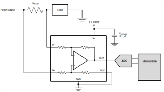
I'm using the INA214-Q1, in the configuration below, for measure the output current of a 0,85V power supply with 2A of nominal current.
I made some tests with a Rshunt=7mohm and the difference between the microcontroller value and the real value (measured on Rshunt) it's 100mA. In other tests done with Rshunt=2mohm (in the same test conditions of Rshunt=7mohm) the difference between the microcontroller value and the real value it's 400mA. The shoftware scale factor is correcti in both measures. Why there is this big difference between two measures? A 2mohm vlalue is too low for Rshunt? The 0,85V power supply output voltage is too low for INA214-Q1 input?

Thanks & Best Regards,

Bruno.

  • Bruno,

    I see this is your first post. Welcome to the E2E forums!

    There's a bit to unpack here, so I'll take it piece by piece.

    First, the output voltage of the 0.85V supply should be fine here. The INA214 works linearly down to a common mode of -0.3V, and here your Vcm would be approximately the output voltage of 0.85V, so this should be fine, provided the common mode doesn't drop below the -0.3V mark. Keep in mind though that the shift away from the datasheet common mode will produce some small amount of additional offset due to the CMRR of the device:

    Next, is your setup exactly as in the SBD you've provided above? I.e., you don't have any input filtration, output filtration to the ADC, etc? A test to try and isolate where the disconnect is is this: take a measurement across the shunt, but then also probe the voltage directly across the pins of the INA214. The voltage at the pins of the device is the voltage that the INA214 will act upon, so it will be good to ensure that the voltage being created at the shunt is indeed making it to the pins of the INA214, and then correctly being amplified to the proper expected output voltage. Filters as I asked about prior can skew this measurement, so I want to rule these out as a possible error source. You may also want to scope this to ensure that the sample and hold capacitance of the ADC is not destabilizing the output, and that the device is sufficiently recovering from the inrush droop when the S&H cap closes. 

    At what part of the scale are you seeing this difference? A 2mΩ shunt will be less accurate at lower amperage than a 7mΩ due to the offset of the device, but there is not really a shunt value that we define as the "minimum" value for a given device. It all comes down to dynamic range and error:


    All of this said, it sounds like the issue you are having is not actually in the measurement itself, but a discrepancy between the output voltage of the INA214 and what is ultimately quantized by the MCU, is this understanding correct? Can you share a bit about the device in use, as well as the sampling rate you are running, resolution, etc. you are using here? Also, can you verify: are you getting the correct output on the INA214, and then the MCU is off by a factor of 100/400mA? 

  • Hi Carolus,

    thank you for the weelcome.
    Between the INA214 output and ADC input there are: a R-C filter with a cutoff freq. =120Hz, an operational amplifier in voltage follower configuration, an voltage divider cactor 0,2 and a 2.2nF capacitor. We measured the voltage across the schunt, to the INA pins 4-5 (input). The values are:
    Vschunt(7mohm)=12,72mV
    V4-5(7mohm)= 13,2mV
    Vschunt(7mohm)-V4-5(7mohm)= 480uV

    Vschunt(2mohm)=3,69mV
    V4-5(2mohm)=4,21mV
    Vschunt(2mohm)-V4-5(2mohm)= 520uV

    Is possible that the difference bwtween schunt measure and INA pin measure cause the current value error?
    what could be causing this voltage difference?
    Thanks!

    regards.
    Bruno.

  • Bruno,

    I think this is certainly a large contributor, but the voltage we're seeing here is a bit shy of the discrepancies you reported above:

    For INA214, G=100V/V, therefore

    480uV*100V/V = 48mV

    520uV*100V/V = 52mV

    This accounts for about half of the discrepancy you report in the 7mΩ condition, but only 16% of the discrepancy in the 2mΩ case, so it seems like there may still be some additional factors at work here. With the additional circuitry on the output, I would also examine the output from the INA and the pins of the ADC, as there may be a similar discrepancy there as well. For the voltage divider leading into the ADC, what tolerance resistors are you using to perform this? You will see an error injection to the measurement in the amount of the actual amount of deviation in the resistance of these resistors (and you should design to the worst case, which would be 2x the tolerance of the resistors).

    Would it be possble to see your layout of the INA and the shunt?