This thread has been locked.

If you have a related question, please click the "Ask a related question" button in the top right corner. The newly created question will be automatically linked to this question.

AFE031: Setting up AFE031 for using FSK modulation

Part Number: AFE031
Other Parts Discussed in Thread: OPA521

Hello,

I am considering AF031 for a my new product development.

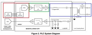
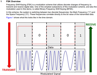
For PLC, I am trying to understand how FSK modulation is carried out by AF031.

I searched TI.com but could not find a document showing such details.

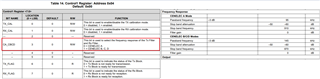
Basically, my question is how do I program AF031 to operate in FSK?

Is there a document showing details on how AF031 transmits digital data using FSK?

Adding further, I am referring AF031 datasheet, and I read below text on 1st page.

It is ideal for driving low impedance lines that require up to 1.5 A into reactive loads.

Could you please elaborate this text from the end application perspective?

Also, to get a reliable performance from AF031, do I have to go with 4 layer PCB(signal + GND + Power + Signal)?

Thank you for looking into this support request.

  • Hi Krunal,

    Q:my question is how do I program AF031 to operate in FSK?

    In the AFE031's register, there are sets of registers, see the image below, which it is enable to select the operating frequency range of EN50065 CENELEC bands A, B, C, D.. This will activate the preprogrammed filter settings in the part. 

    Enclosed is a EVM link and MCU application note for AFE031. 

    There are two unique higher frequencies that represent "1" ad "0". Binary digital signals of 1 and 0 are converted to sine signals in analog frequencies that are sent through power amplifier inside of AFE031 IC, see the image below. With proper analog signal coupling techniques, the high analog frequencies are coupled onto an existing powerline (AC or DC power line), and transmitted over a distance to other end of powerline. The receiver side of AFE031 is converted the high  frequency signals, filter out the unwanted information, demodulated it via ADC and convert the transmitted signals back to binary digits into 1 and 0.  This is a simplest way that I can explain it, but actual sequences are a lot more involved than the description above. 

    Regarding AC or DC power: AC powerline can be 50/60Hz powerline with 100Vrms to 220Vrms or even higher in industrial power lines. DC powerline can be low voltage DC, solar voltage powerline to several hundred voltages or even kV range in DC powerline. The Signal coupling methods are different from DC to AC powerline, we can discuss various coupling methods, if you are able to tell me your applications. For instance, The blue rectangular is  a transformer coupling techniques to couple transmitted B-FSK signal onto AC powerline. AFE031's side is DC voltage up to 24Vdc, and powerline side is a standard AC powerline, say 60Hz, 115Vrms power.

    https://www.ti.com/lit/ug/sbou223/sbou223.pdf?ts=1618844676480&ref_url=https%253A%252F%252Fwww.google.com%252F

    https://www.ti.com/lit/an/sprac94c/sprac94c.pdf?ts=1618845253264&ref_url=https%253A%252F%252Fwww.google.com%252F

    https://www.ti.com/lit/ug/tidue68/tidue68.pdf?ts=1618850038313&ref_url=https%253A%252F%252Fwww.ti.com%252Ftool%252FTIDA-060001

    Q: It is ideal for driving low impedance lines that require up to 1.5 A into reactive loads. Also, to get a reliable performance from AF031, do I have to go with 4 layer PCB(signal + GND + Power + Signal)?

    AFE031 is integrated an precision power amplifier or OPA521 at its transmitter side. Power amplifier's current rating is up to 1.5A and can drive resistive load, capacitive or inductive load. When AFE031's transmitted signals are coupled to a transformer, for instance, transformer becomes a load that AFE031 has to drive. Transformer load consists of R, L and C, which is a complex load or it is called reactive load. When a regular power amplifier drives a reactive load, the op amp will require additional feedback loop compensation in order to keep the op amp stable. AFE031's power amplifier does not require additional feedback loop compensation for the PLC application. In other words, AFE031 is able to drive a typical reactive load, like transformer up to 1.5Arm without additional feedback loop compensation. 

    Regarding to layout, I recalled that AFE031's EVM is 4-layer board design, which is a standard practices these days. Can you use 2 layer PCB layout in the design? Perhaps, but I won't recommend it. If you need any assistant regarding the layout, please let me know. 

    Best,

    Raymond

  • Thank you Raymond for taking time and replying to my queries.

    I do have certainly additional queries but let me proceed further.

    Take care and thank for sharing the information.

    Regards,

    Krunal