This thread has been locked.
If you have a related question, please click the "Ask a related question" button in the top right corner. The newly created question will be automatically linked to this question.
Part Number: THS3092
Tool/software: TINA-TI or Spice Models
Hi, TI employee
I need some guidance from you.
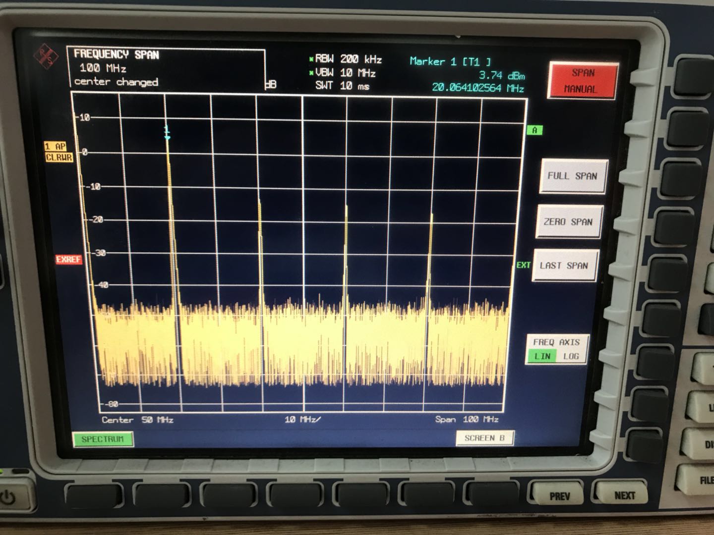
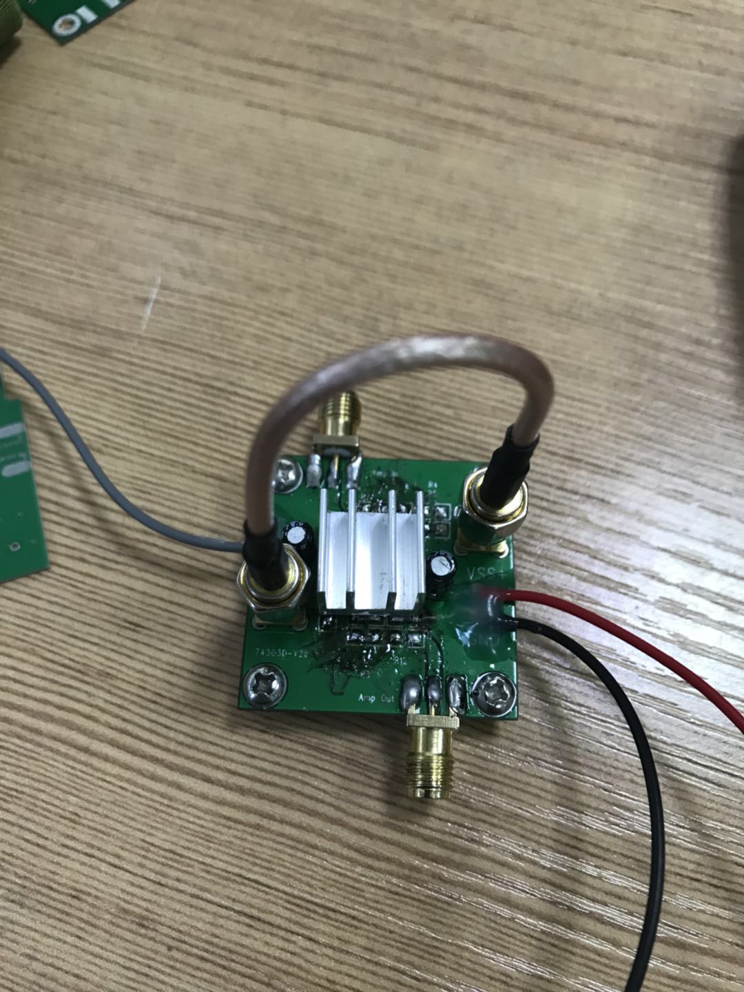
I’m making a design for amplifying a 20 MHz 200 mVpp signal to 10 Vpp using THS3092 and want to drive a signal generator connected by a 50 ohm coaxial cable. I want to use this single chip to do two stage amplifier with gain of 50 V/V. But in order to meet impedance matching, the gain of even 100 V/V will reduce to 25 V/V. When followed by the datasheet, the max amplification factor is 10 V/V, for larger gain there is no recommend Rf value. So here is my question:
1.Can I use this single THS3092 to meet my design?
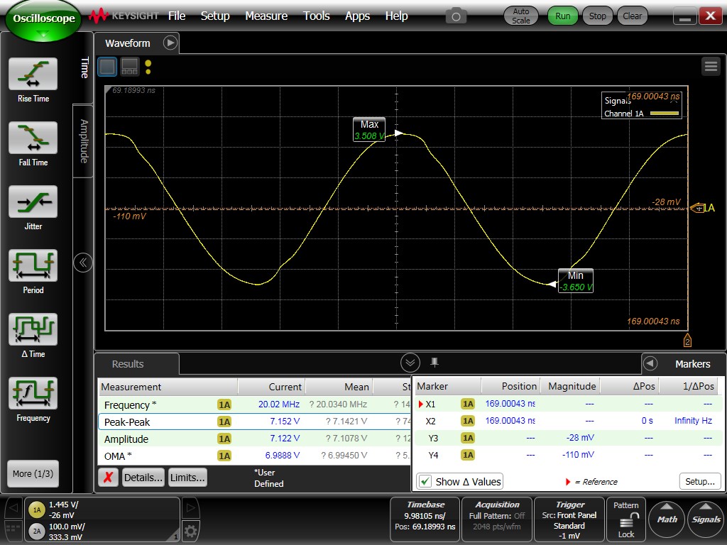
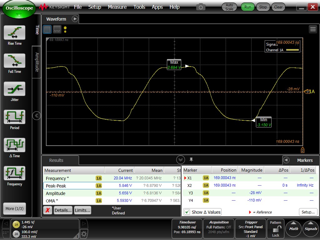
2.If I want more gain than 10 V/V, like 15 V/V, is there any recommend value for Rf and Rg?(p.s. I have try some value but the output waveform is distorted and the peak can't reach even 6 Vpp. The power supply is ±12 V)
Thank you for your help, I'm waiting for your reply.
In reply to Sean Cashin:
Hi Sean,
Thank you very much for your reply.
I have try your recommendation in my circuit. But I get a sine wave with distortion as Fig1 in the attachment. Fig2 is the spectrum test result.
Then I reduce the Rg in first stage to 54 ohm, the second stage's Rg is remain 66 ohm. The result seems Ok but still have little distortion. As you can see the result in Fig3.
I think the datasheet says in power supply ±10 V, we can get 12 Vpp signal at most. So I reduce the power to ±10 V, the result is in Fig4 and it seems to be restricted by ±3 V.
Here are my two questions:
1.What may makes the harmonic distortion happen?How can I do with it?
2.Why my signal being restricted by a value of power which much less than the datasheet says?What’s the important point I have missed?
Thank you again and I'm hoping for your answer.
Best Regards!
Kirk
Fig1:
Fig2:
Fig3:
Fig4:
In reply to Kirk Lin:
Thank you for your recommendation.
I'm not sure what's the meaning of internal impedance? Is it the impedance between these two stage ? Now I'm doing a demo circuit and all the ports are connected by coaxial cable, the impedance for all ports should be 50 ohm, so if I use 100 ohm or higher impedance, there may cause mismatch. Does that means If I layout the PCB next time and connect the two stages straightly in microstripline and change the impedance matching then I can get more stable output?
Here is my circuit:
I will try more and then update my progress for more advice. Thank you again for your help.
I've tried some value of Rf and R4 and finally got the 10 Vpp signal. I missed one point that because the load of 50 ohm transmission line, I need 20 Vpp output for sharing half power to the load. In ±12 V power supply, I can get nearly 14.4 Vpp signal output for most before load. So I can only get some distorted signal and limited by 7.2 Vpp when connecting to SMA cable. After I enlarged the power to ±15 V, I can get the sine shape I wanted.
Sincerely thank you for helping me all the time.
Best regards!