This thread has been locked.

If you have a related question, please click the "Ask a related question" button in the top right corner. The newly created question will be automatically linked to this question.

LM2907-N: Creating A Simple Frequency to Voltage Converter Circuit

Part Number: LM2907-N
Other Parts Discussed in Thread: VFC320, LM2917-N

I'm having trouble developing a circuit that will simply turn an RPM signal into a 0-5 V signal.

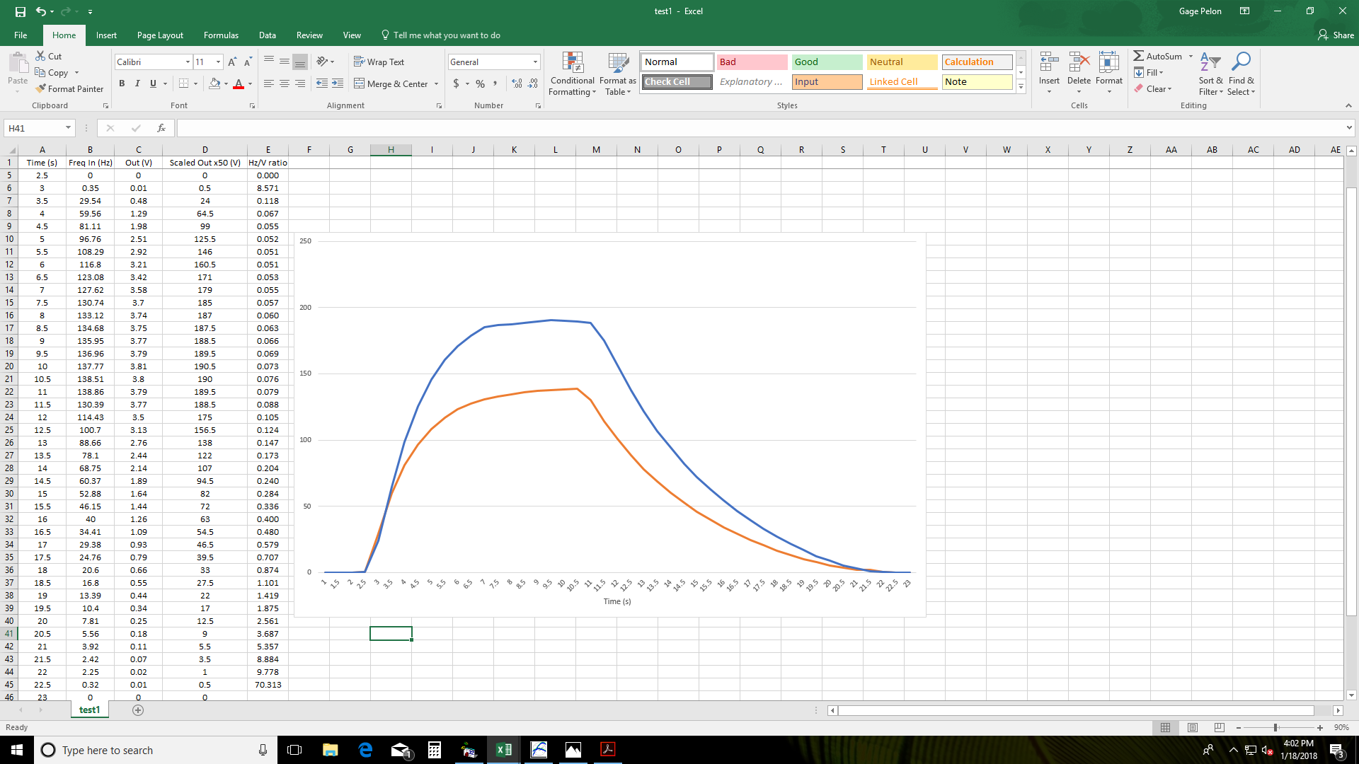
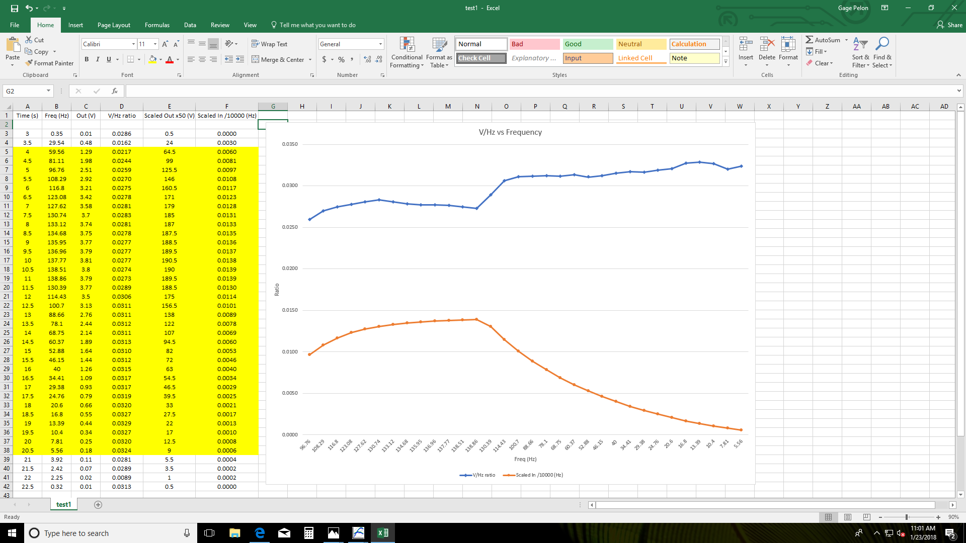
The supplied voltage is 12 V and the max input frequency is 50,000 RPM. The output voltage needs to be between 0 and 5V.

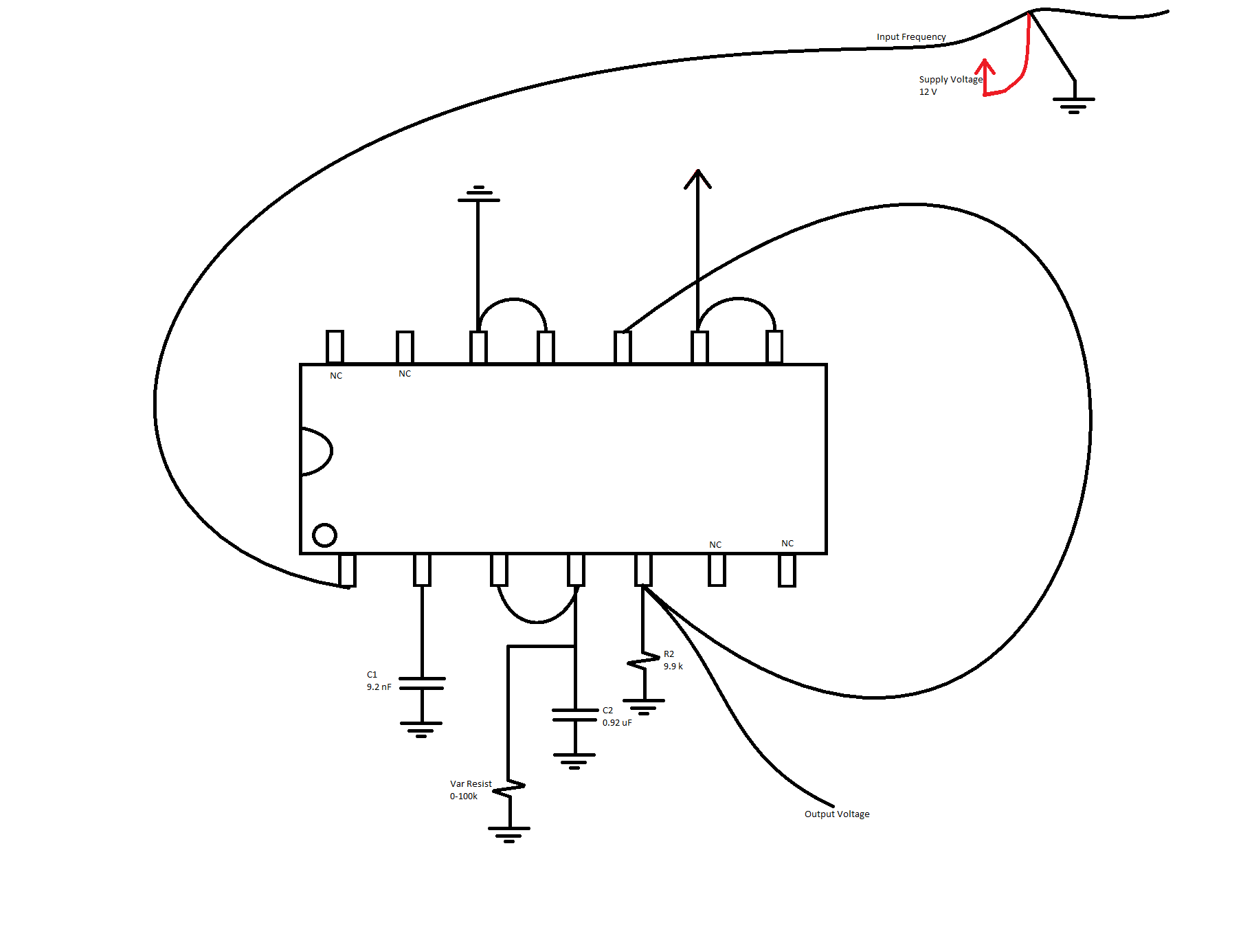
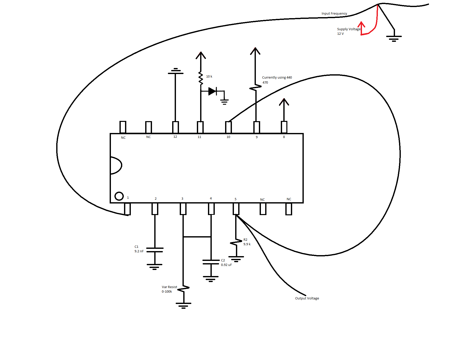
I've already tried to use the Minimum Component Tachometer Diagram on the first page of the data sheet - only changing the R's and C's to meet my specs from above - with no luck. 

Thanks in advance,

GageLM2907.pdf

  • Hi Gage,

    You indicate that you had no luck with the LM2907-N minimum component tachometer circuit. Did you find that to be the case over the entire RPM range of your application, or just in the range of 50,000 RPM? All indications in the LM2907-N datasheet and application note (AN-162) is the LM2907-N top end frequency is about 10 kHz. For example, see Figure 10, RC Selection Chart in AN-162. 

    This application note provides a lot of good information about applying the LM2907-N in various tachometer applications so it would be good to review it in relation to what you are attempting to accomplish with your circuit.

    If it turns out to be a maximum frequency issue with the LM2907-N, about the only higher bandwidth solution I can suggest is the VFC320 V-F converter. It can be configured as a wider bandwidth F-V suitable for 50 kHz, but would require a dual +/-15 V supply for power.

    Regards, Thomas

    Precision Amplifiers Applications Engineering

  • Thomas,

    I had no luck with the LM2907, regardless of the input frequency. Also, the max RPM at the input would be 50,000 RPM which is about 833 Hz, therefore the upper limit shouldn't be an issue.

    Currently, the type of signal we have at the input is an open-collector signal (0 to some positive voltage), but I'm not sure if this converter requires a "zero-crossing" signal. Does this converter detect zero crossings, or should this not matter?

    I'll read over the PDF that you sent over to see if I did something wrong - I was just hoping someone would have a simple solution to this.

    Thanks,

    Gage

  • Hi Gage,

    Yes, you are correct 833 Hz (not 50 kHz as I was thinking) and that should be well within the capability of the LM2907-N.

    The LM2907-N tachometer to voltage converter circuits are straightforward and should work if everything is set correctly. Not that it should make much difference, but are driving the TACH+ pin 1 input with a variable reluctance magnetic pickup or some other source of voltage that provides an indication of speed?

    If you can provide your original LM2907-N tach circuit listing the selected component values, we review it.

    Regards, Thomas
    Precision Amplifiers Applications Engineering
  •  Thomas,

    For the input, I have a frequency generator (using an open-collector signal) capable of producing anything between 0 and 1kHz. I made a quick diagram of my setup in Paint and will post it. Currently, I have the variable resistor set for 50 k. Also, I have the 14 pin version so my configuration is a little bit different than the diagrams in the data sheet.

    Using the Vout equation given in the data sheet and my current components, I should get the following:

    VOUT = fIN × VCC × R1 × C1

      = 1 kHz x 12 V x 50 k x 9.2 nF

      = 5.52 V

    Actual Vout=0


    Thanks,
    Gage

  • Hello Gage,

    One of our Application Engineers from the original National Semi group spotted something with your LM2907-N circuit, and it is likely the reason it didn't function as expected.

    You are using the 14-pin device and the TACH- (pin 11) is hardwired to GND in your circuit. He indicated in that case the input signal applied to the TAC+ (pin 1) must then cross through 0V with an amplitude of at least ±30mV to overcome the internal hysteresis. "If he has a TTL input, it will not cross down through zero, and may not even make it to +30mV. He needs to raise the comparator reference voltage above ground on pin 11 (see Fig 21)."

    Datasheet Figure 21 shows how a 10 k resistor and a silicon diode are connected to pin 11. Doing so raises the reference voltage 600 to 700 mV above GND. The TLL input signal applied to the TACH+ input will then swing across the reference voltage level set on the TACH- input. The comparator will then be able to switch as needed.

    Regards, Thomas

    Precision Amplifiers Applications Engineering

  • Hi Thomas,

    I apologize for the delayed response. I appreciate you and your teams insight! We had a feeling that the zero-crossing was going to be an issue, but weren't sure how to change it. A few more questions:

    1. Would the reference voltage be able to be configured via a voltage divider instead, in the case that we wanted a difference reference voltage? 
    2. Is B+ referring to a +12 V supply voltage?

    Thanks again for all of your help,

    Gage

  • Hi Gage,

    No problem, here are some answers to your LM2907-N questions:

    1. Would the reference voltage be able to be configured via a voltage divider instead, in the case that we wanted a difference reference voltage? Sure, a voltage divider can be used instead of the series resistor and forward biased diode. You should be able to use any reference level within the comparator's input common-mode voltage range. The Electrical Characteristics table 7.5 lists the input common-mode voltage range as 0 V to VCC–1.5 V.
    2. Is B+ referring to a +12 V supply voltage? It is interesting that the Vcc designation used for the 8-pin package is changed to B+ for the 14-pin package applications shown in datasheet Figures 20 through 22. Vcc and B+ are the positive supply voltage being used in the particular application. For either power supply designation the practical supply voltage range is 6 to 24 V, with 28 V being the absolute maximum.

    Regards, Thomas

    Precision Amplifiers Applications Engineering

  • Thank you so much for clearing that up. I've edited my diagram and posting it here just incase someone comes across this thread in the future.

    Thomas, you have been a huge help and I appreciate everything!

  • Everything works on the F to V converter! But now I am having a different issue:

    I tested this circuit on a grinder and it seems very shakey. It isn't a steady curve whatsoever and I'm wondering if that is normal? Overall the curve is similar to what it should be, but it is constantly going up and down a few percent during the test. 

    Also, the curve is delayed by a few tenths of a second between the true Hz and the voltage curve. Is this typical?

    I am attaching a snapshot of a spreadsheet that I made so you can see the delay that I'm talking about, but the data is only sampled every 0.5 seconds so you wont be able to see the shakiness that I was talking about. Also, I scaled the output voltage by 50 to show that it compares to the Hz input.

    Thanks in advance,

    Gage

  • Hello Gage,

    I am not sure what you mean by a "grinder" except for possibly a grinding wheel used in machine shops?

    I do expect the LM2907-N perfomance to be predictable and repeatable. The LM2907-N input is an analog comparator that will respond to small differences in the input level on the TACH+ input, relative to the reference input on the TACH- input. If there is variation in the input signal the voltage in relation to time, the LM2907-N output voltage will track with it. Noise riding on the input signal can lead to this uncertainty. You don't mention what sort of assembly the LM2907-N is part of, but make sure that it is properly housed in shielded enclosure if there is the possibility of noise getting into the comparator inputs. The shielding should be extended to any input line, coax or twisted pair, from a transducer.

    Be sure the supply voltage applied to the LM2907-N is well regulated and free of noise. One of the reasons for the LM2917-N version of the product and the inclusion of the internal zener regulation is to assure a more constant Vcc level in loosely regulated appications.

    The datasheet doesn't mention anything about the time required to accomplish the tachometer-to-voltage conversion, but it stands to reason that the charge pump circuit requires time to charge and discharge when converting the input pulses to a dc level. Certainly, if you are observing delay it is a normal characteristic of the conversion process.

    Regards, Thomas

    Precision Amplifiers Applications Engineering

  • Hello Gage,

    Also, best performance is obtained when the input signal applied to the TACH+ input is centered about the reference level (TACH- voltage) and is a symmetrical waveform.

    Regards, Thomas
    Precision Amplifiers Applications Engineering
  • In the photo above, I graphed the V/Hz ratio vs the input frequency (highlighted portion only, ignoring outliers). The data sheet claims to have +/- 0.3% linearity, but that isn't the case here. Just wondering what could cause this? Also, the orange line is the frequency and you can see that right after the peak frequency, the ratio jumps up quite a bit - almost like its experiencing some sort of hysteresis. 

    Using a scope, I watched the input frequency. It stays high at 11 V and dropped to 0 once per revolution. Does the converter expect this signal to be inverted, staying at 0 and jumping to 11 V once per rev?

    I'm also exploring the option of using Figure 27 from the data sheet. It claims that it reduces ripple which seems to be exactly what I need. I'm just having trouble decided on R and C for that circuit. Thoughts?