This thread has been locked.

If you have a related question, please click the "Ask a related question" button in the top right corner. The newly created question will be automatically linked to this question.

INA125: Problem with linearity and temperature stability

Part Number: INA125
Other Parts Discussed in Thread: LM7705

Hello.

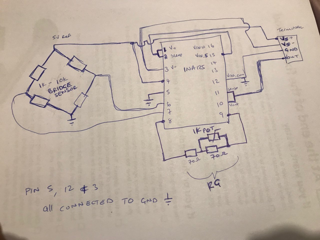
I am using the Texas instruments INA125 chip for an analogue amplifier as I have shown on the attached image. INA125 data sheets says Nonelinearity -+0.002% of FS at Gain = 500 
I am trying to use both the single and dual supply modes by connecting Vs- to ground or to a negative supply
The Dual supply operation seems to work fine (I have connected it almost identical to figure 1 of the INA125 data sheet) Its giving me an acceptable linear output 0.07% of FS for a gain of up to 4000.
The Problem is when I connect it in a Single Supply Mode (Figure 5 of the data) with V-,VrefCom and IAref all connected to ground. The linearity is way out of spec (I am getting 1-3% of FS) and I have a minimum output of around 65mV (even placing offset adjustment resistors I cannot go below this value in single supply mode).
I also measured IAref before connecting it to ground at it was = 2.5V. A bit like in figure 6 of the data sheet, but how is this possible if I did not connect IAref to Vref2.5. I have a feeling watever the problem is, it probably has something to do with this IAref, but I cannot seem to know why..please help!

My application is for a 0-10V output or 0-5V output. I am using minimum 7V input for the single supply 0-5V and 12V for 0-10V. The Maximum I am using is about 32V.
I do not have a load on the output, I connected a DMM +terminal to Vout and negative terminal to gnd.

I think the data sheet says when the load is referred to ground as shown (figure 5), the actual output voltage swing is limited to approximately 150mV above ground. Is this the reason why I am getting a minimum of 65mV instead of Zero only in single supply operation.  Is this also why I am not getting good linearity?

If this is true, Is there a way around this other than maybe to have a 0.15V - 5.15V and a 0.15 to 10.15V output? It would really be great if I can have a 0-5V and 0-10V output, is there any other way around this if this is the problem?

  • Do you have any suggestion of maybe additional circuit that I could add like a power supply converter? this would need to work for supply voltages of (7V to 12V) Minimum and (32V or 36V) Maximum.
    Another thing is I could use the IAref (which is 2.5V without being connected to anything) as my output reference. So that I can have my outputs as 0-5 or 0-10V (in reality they will actually be 0-2.5V and 0-7.5V if referenced to ground). Will this be a bad/wrong thing to do? I will just have to make sure that instead of 7V minimum for 0-5V output I can say maybe 10V minimum to power the circuit?

  • Kev,

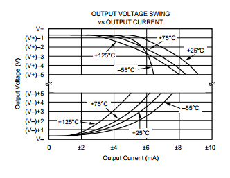
    No output of an amplifier may swing all the way to the negative rail becuase this would only be possible if no current flows in the output stage but there is always a minimum of quiescent current present.  This is shown in the graph of the output voltage swing vs output current below.

    For that reason, in order to obtain a linear performance for the entire output voltage range, you must reference the output voltage at least 150mV above the negative rail resulting in 0.15V to 5.15V output range you refered to. An alternative approach resulting in 0V to 5V range, would require a negative supply or to use LM7705 (a negative charge pump with -230mV output) to bias the negative rail. 


  • Hello.
    Thank you for taking your time, much appreciated.
    Just so I can be clear, you mean I should connect the output of the LM7705 (-230mV output) to Pin 3 of the INA125?
    It also says that the LM7705 needs 3-5V so can I use the reference Vref_5V from the INA125? Which I am also using to provide a 5V excitation to the sensor. The data sheet also says it has a 5% tolerance, will this cause other problems at all since my circuit does need to operate from 25 deg C to 85 deg C
  • Please see my answers below:

    Just so I can be clear, you mean I should connect the output of the LM7705 (-230mV output) to Pin 3 of the INA125?

    Yes, that's correct.  The output of LMV7705 should drive the negative supply of INA125 (pin 3).

    It also says that the LM7705 needs 3-5V so can I use the reference Vref_5V from the INA125? Which I am also using to provide a 5V excitation to the sensor. The data sheet also says it has a 5% tolerance, will this cause other problems at all since my circuit does need to operate from 25 deg C to 85 deg C.

    Yes, you should be able to use Vref_5V from INA125 as a supply voltage for LM7705 - the reference voltage of INA125 has +/-0.5% accuracy, not +/-5%, but regardless, it should not effect the proper operation of the circuit.

  • Hi.

    Thanks for the reply.

    a. I am using a single power supply 7V-32V connected to pin 1 and pin 3 is connected to ground.

    b. I connected Vref_out (pin 4) to Vref_5V (pin 15) so that I get a 5V precision reference which I am using for bridge excitation.

    Can you please explain to me the following observations:

    Question 1.

     c. If I do not connect anything to IAref (pin 5), I get a 2.5V output with no load (Pseudoground 2.5V?). Does this mean internally the chip connects IAref to 2.5V,meaning Vo = 2.5 + (xxxxx) if measured between IAref and pin 11 or for the pseudoground has to be connected to something?.

    How come in the data sheet figure 6 the IAref (Pin 5) is physically connected to Vref_2.5 to get a pseudoground of 2.5?.

    The reason I am asking is I cannot connect my circuit as figure 6 because I need the Vref_5V for bridge excitation. If the IAref is = 2.5V as I have mentioned above, can I just use this pseudoground and measure my 0-5V or 0-10V output? The only problem would be the output will actually be 0-7.5V and 0-12.5V if measured from ground so I would need a minimum Vsupply of approx 9V for 0-5V and minimum supply of 14V for 0-10V output. Is this not a way to solve my problem without having the additional circutry and a redesign using the LM7705 (Which I also am not sure if the -0.23V will be enough or I could require more than this?)

    Question 2. 

    d. If I connect IAref (pin 5) to Vref_5V (pin 15) I get a 5V output with no load (Pseudoground 5V) similar to datasheet figure 6. 

    How come even if I increase the gain and increase input voltage in this configuration I cannot get an output above approx 9V? (measured between IAref and Vout)..is this because Vo = 5 + (9) = 14V and this is the maximum swing I can get with pin 3 connected to ground?)