This thread has been locked.

If you have a related question, please click the "Ask a related question" button in the top right corner. The newly created question will be automatically linked to this question.

INA103: Output voltage of the INA103 is wrong with gain setting G=1

Part Number: INA103

Dear all,  if would be of great help if someone here can help us to get out INA103KP running properly. Since weeks we can't understand what is wrong.

We're using INA 103 KP  as instrumentation amplifier as driver for thermocouple circuitry. We wired it up as the datasheet suggests in Figure -1. That said, V+/V- = +12/-12 DC, Gain = 1, pin 14 is left open, then pin 2 and pin6,  pin15 and pin13 are tied together, then pin10 and pin11 are tied together. Pin7 is connected to Ground. The input terminals pin1 is analog signal from thermopile and pin16 is negative signal from themopile. In this configuration as soon as power is supplied INA 103 outputs 12Volt on its pin 10. if we measure the thermopile signal before entering to INA103 its 100 mVolts. In this case with G=1, we should get 100mVolts at INA103's output. It looks like it just outputs 12Volts even if i remove the signal source.

hope someone can make a light in this darkness.

David

  • Hi Dave,

    Do you have a path for input bias current from both INA103 inputs to ground? I suspect that if the thermocouple is floating, bias currents on the INA103 are pulling the inputs to either the positive or negative rail, causing the INA103 to violate its common mode range and causing unpredictable behavior. Tying the - input to ground (either directly or through 10kΩ-100kΩ) should fix the issue. 

  • Hi Alexander,

    thanks for reply.

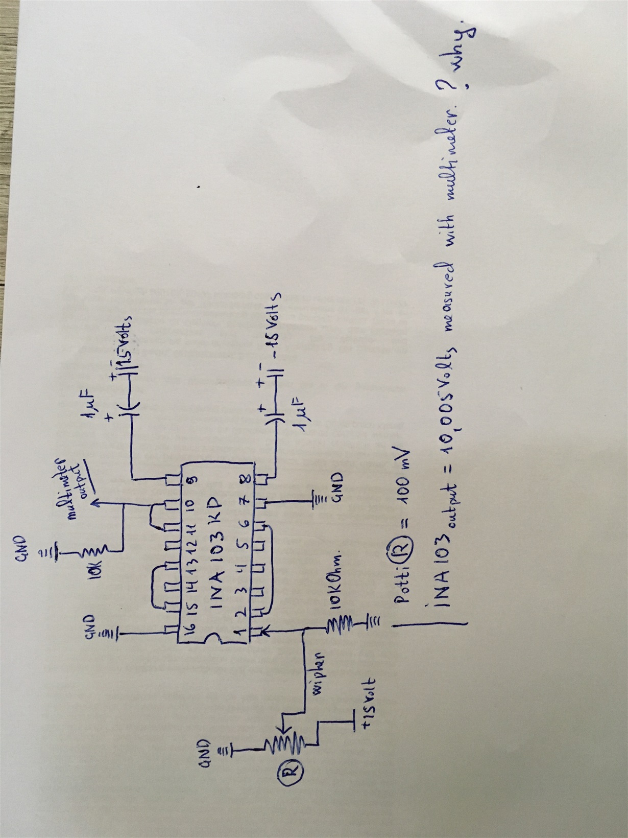
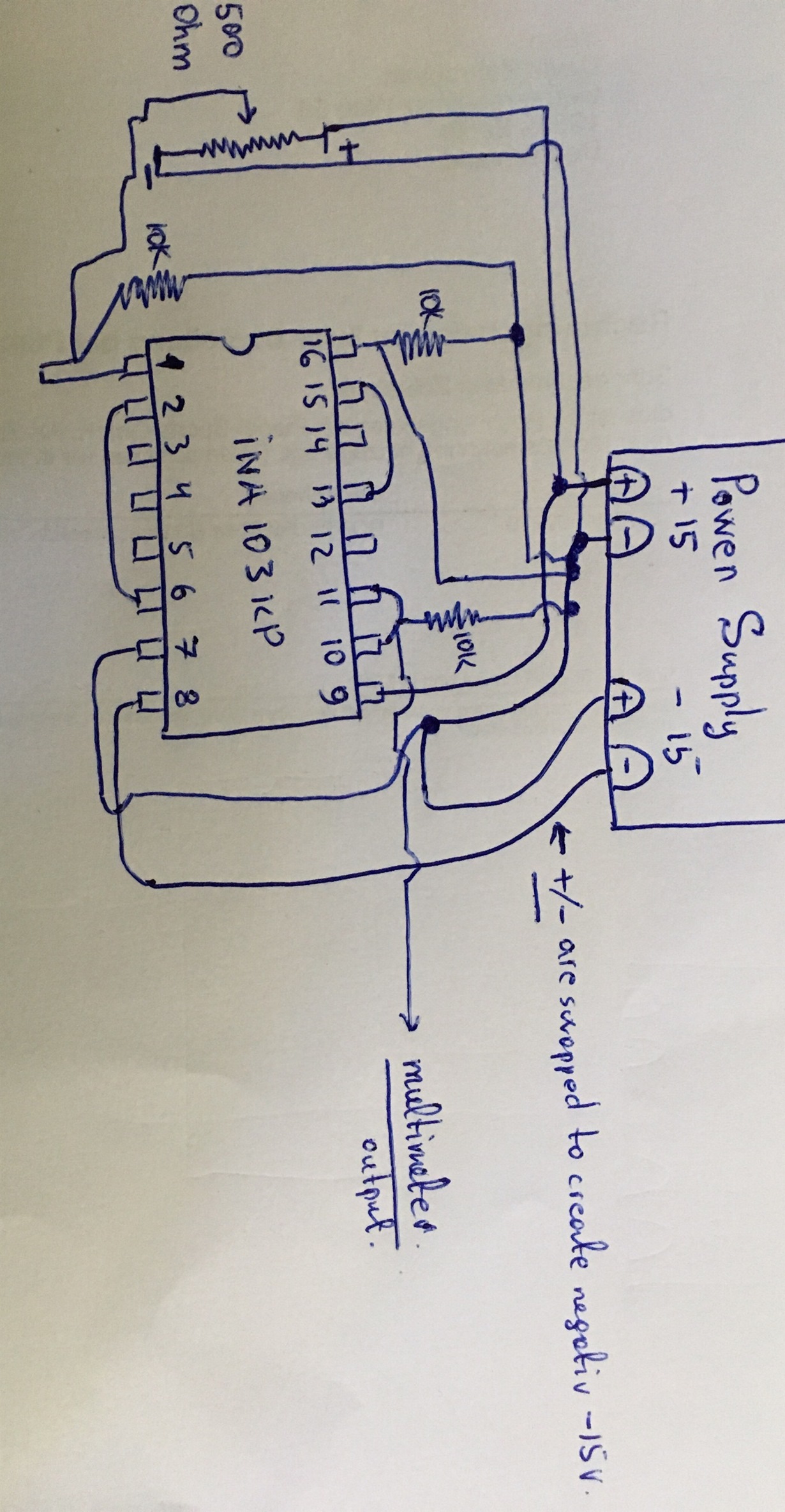
    I decided to remove the thermocouple and try something simple to troubleshoot the issue. So I have placed a 500 Ohm potentiometer instead of thermocouple. Please have a look at the schematics. Even if the signal from wipher is 100mV, and Gain is set as G=1, INA outputs 10 Volts on pin 10. If I start turning the potti wipher the output start to change as well, but it never goes to a value close to zero, or the one which potti wipher outputs. When I turn the potti all the way, the INA 103 output start from 10Volts, then decreases until 1.1 Volts and then if I continue rotating potti it stays at 1.5Volts.

  • Hi Dave,
    That is unusual. Could you measure the voltage at pins 5 and 12? Also, if you could provide waveforms at pins 5, 10, and 12 measured with an oscilloscope, that might be helpful. We've seen errors before where a DC shift when measured with a DMM, when the real issue is actually an oscillation in the device.
  • Please confirm that in the real world circuit +15V supply is connected directly to Pin 9 and -15V supply is connected directly to Pin 8. This is not confirmed by looking at your paper schematic picture.
  • Hello Tim, please have a look at the updated schematics. The pins (8 and 9) are attached to power supply which has two outputs. I have connected the +15 Volts to INA103's pin9 and -15 Volts are supplied through swapping the other output's (+\-) lines.  When the power is supplied to circuitry the value measured at output pin with regular multimeter Agilent 1272, show 12.6 Volts, and nothing happens even if I rotate the potti wipher.

  • Hi Dave,

    I think the chip was damaged during the experimenting with it. Take a fresh INA103.

    Use allways power supply decoupling caps, experiment only with both supplies permanently connected to the INA103. And insert a 100R resistor in the output line when you connect cables to the output.

    Kai
  • Hello Kai,
    actually on the very first topology I used tantalum 1 mF decoupling capacitors for both -/+ power supplies. Considering my last post with picture, It should have shown 100mV on its output pin, if the analog signal from potti wipher was at 100mV. Is it possible that I have connected something wrong?

    Dave
  • Hi Dave,

    yes, in the first picture the decoupling caps were connected incorrectly. You have put them in series to the supply inputs. But you must put them in parallel, one leg of decoupling cap to the supply pin and the other leg to GND.

    Kai
  • Dave

    We haven't heard back from you so we assume you were able to resolve your issue. If not, post a reply below, or create a new thread if this on has timed out.

    Thanks
    Dennis