


Other Parts Discussed in Thread: OP27, OPA140, OPA4227
Hi team,
The customer uses OPA4140 to design an instrumentation Amplify circuit and a voltage follower circuit.
Please check his TINA circuit in the attach.
1. In his actual circuit, if the customer remove the high-pass filter circuit (that is C12,C13 and R32 ),
the figure 1 is VF1 waveform. the figure 2 is VF3 waveform. From the VF3 waveform, there is some glitch waveform.
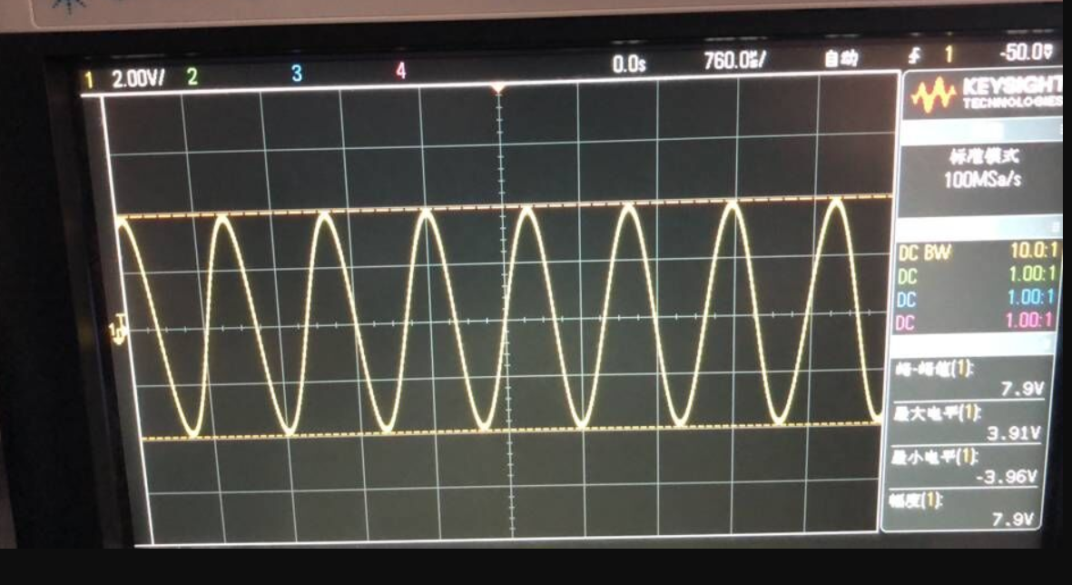
Figure 1 VF1
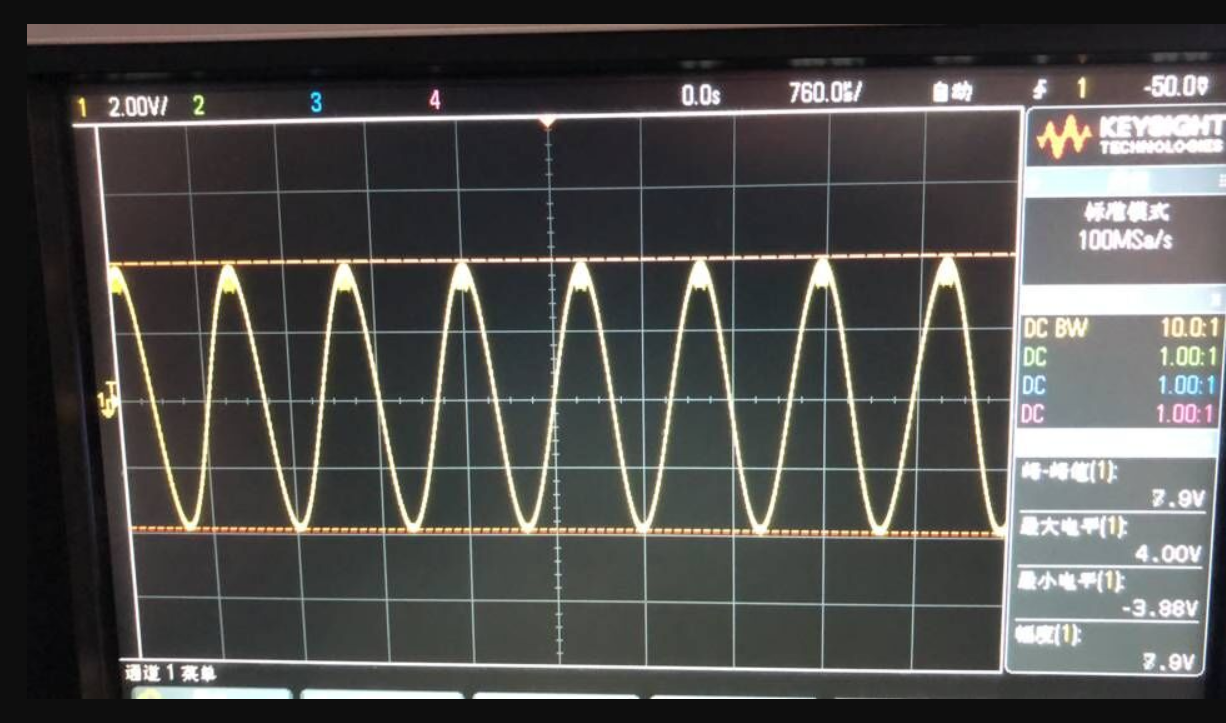
Figure 2 VF3
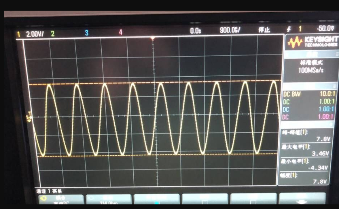
2. If the customer adds the high-pass filter circuit, the figure 3 is VF1 waveform. the figure 4 is VF3 waveform.
Compare to figure 3 and figure 4, the customer found the VF3 waveform moves down than VF1 waveform.
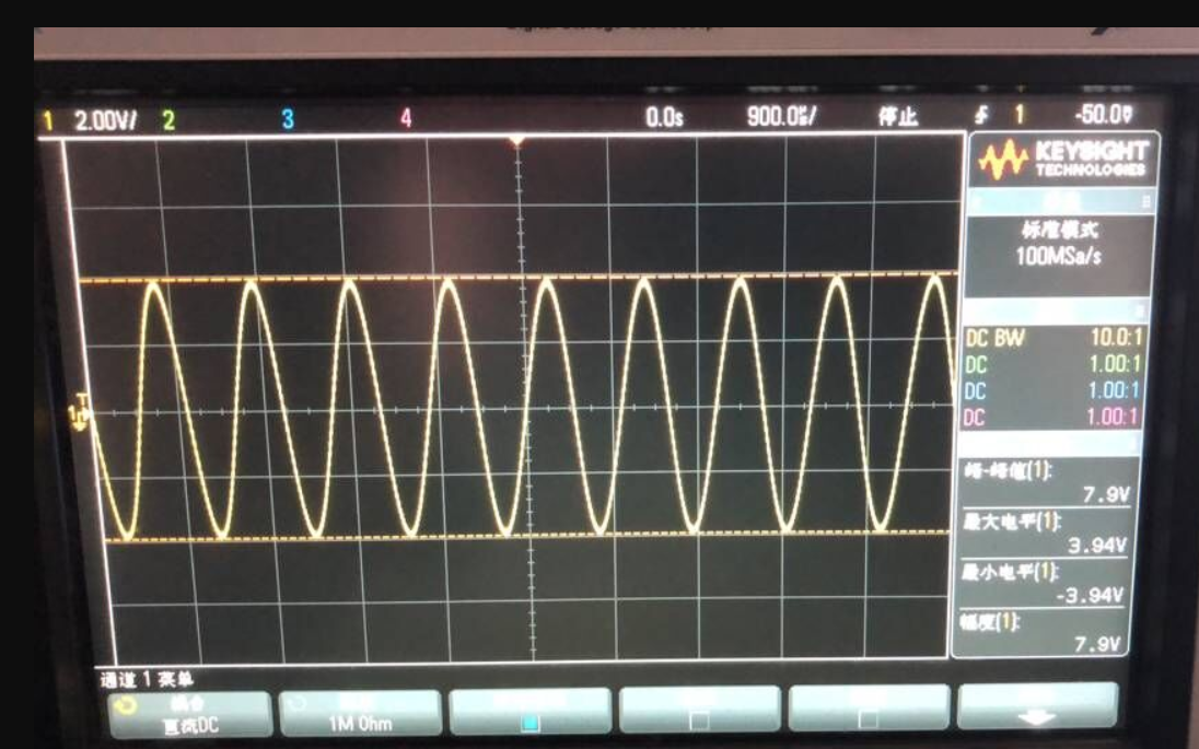
Figure 3 VF1
3. If the customer change R32 to 3K. Figure 5 is VF3 waveform. The amplitude of VF3 moving down is reduced.
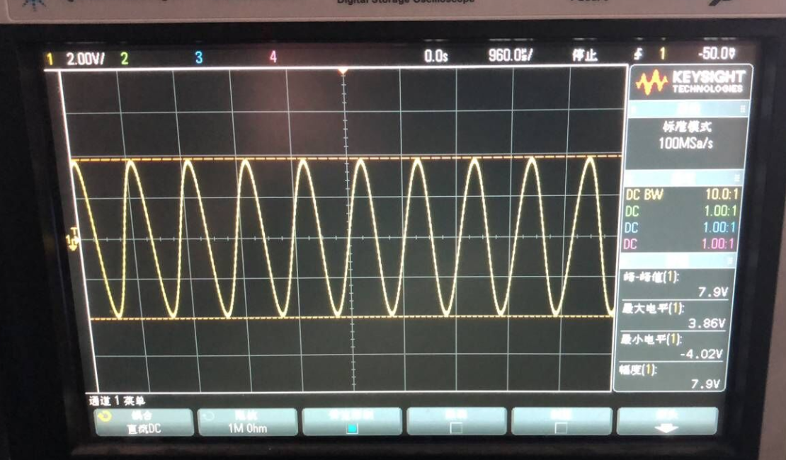
Figure 5 VF3
4. If the customer keep R32 be 32k and remove C12 and C13, the VF3 waveform will not move down and
keep the same with VF1.
5. If the customer adds the amplitude of VF1, VF3 waveform will be moved down.
6. If the customer uses OP27 as the voltage follower circuit, VF3 will waveform will not move down.
Would you explain why VF3 waveform can be move down?


