Because of the holidays, TI E2E™ design support forum responses will be delayed from Dec. 25 through Jan. 2. Thank you for your patience.

This thread has been locked.

If you have a related question, please click the "Ask a related question" button in the top right corner. The newly created question will be automatically linked to this question.

Why are they different? sensorless and sensored BLDC waveforms with DRV8312-C2-KIT


Hi everyone,

I am a little confused about the different waveforms for sensorless and sensored control of BLDC, motor not loaded.

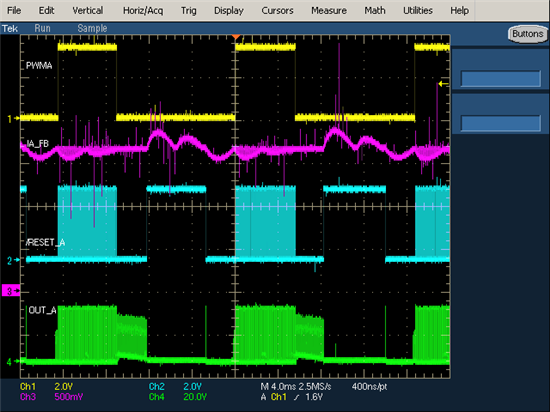
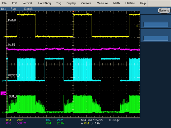
I got the waveforms for sensored (left) and sensorless (right) control of BLDC with CCSv4.

Yellow: PWMA

Purple: IB_A

Light blue: /RESET_A

Green: OUT_A

Sensor or sensorless, the differece is the calculation/estimation of the rotor position. I don't understand why the OUT_A for sensored and sensorless so different.

Could somebody point it out for me?

Long

  • Long,

    I looks to me like the Sensored is not communtating at the correct time. Sensored methods can only communtate as well as the sensors will allow it, so this may add a slight delay in the communtation time. You can tell something is going on with the Sensored waveform since the current is so high and also durning one of the off states of the Reset A signal there is no current at all, when it should be similar on both sides of the PWMA High pulse.

    LT

  • Hi LT,

    thanks for your suggestion. I checked the signals from hall sensor. They are ok!

    I just don't understand, with the same PWM signals as input, why I got 2 different outputs.

    If the commutation was not at the right point, then PWM singals should also start earlier or later, but in my case, they are totally the same in the both case.

    The Back-EMF in sensored control is not a trapeze, by the way.

    Did anybody get the same result with DRV8312-C2-KIT?

    Long

  • I got the same result for the Sensored part. I am wondering why the current waveform looks like that. I am expecting that after the 2 humps, it would be flat (or zero) then goes down.

    Do you know why?
  • Hi LT,
    I see the same plots give by Long.

    Can you give suggestion on how to correct this commutation problem?

    Thanks!
  • Figured out. Wrong CmtnPrd set.
  • Thank you for following up. What CmtnPrd did you use?
  • Long,

    I just come across a very similar issue from other customer about a sensored application which got the waveforms just like yours.

    After checking all aspects, we identifed the issue is because of the Hall sensor sequence and its polarity.

    I think you have tried all the sequence of the three Hall sensors or the three U V W outputs connections and now you get what is the "best" you can achieve. But actually this may be not the "best", even not the correct one. You can just try to get all the Hall sensors outputs reversed. That means a 180 degree phase change which can't be compensated by only change the sequence of the Hall sensor which only gives 120 degree change. So you are now actually 60 degree phase lag or advance to the correct sequence and polarity.

    Note that after you have changed all the Hall sensor polarity, you should retry all the sequences. A simple way is just swap the U V W to V W U or W U V. A 120 shifting for either direction, there should be one which is the correct one. After all is done, you can get the similar waveform just as normal and similar to the sensorless one. You will also get a lowest supply current of the motor in open load condition compare to what you can achieve now.

    Best regards,
  • Hi Wilson and Rick,

    Is there a way to improve the range of speed setting and accuracy for the sensored? How is it possible to set the motor still running at say 10 RPM for both sensored and sensorless?

    Why is there such a difference between sensorless and sensored (refer to data below)?


    Speed Setting in RPM Measured Speed in Sensorless (Range in RPM) Measured Speed in Sensored (Range in RPM)
    367 361-369 332-399
    350 344-353 307-385
    332 326-337 284-358
    278 272-284 max 369 (motor stops)
    224 215-237
    189 169-205
    170 120-238 (motor stops)

    Hope you can investigate this and provide feedback.

    Thanks!