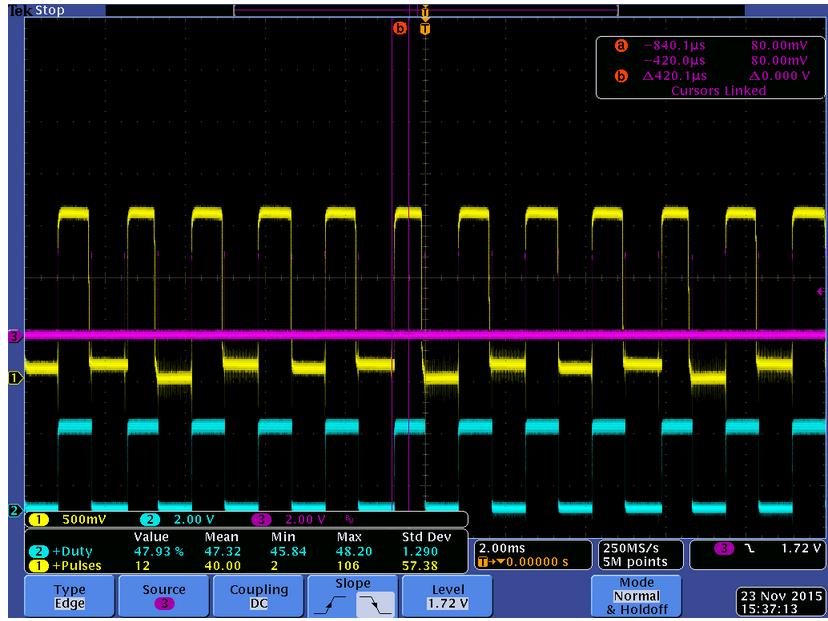
This thread has been locked.

If you have a related question, please click the "Ask a related question" button in the top right corner. The newly created question will be automatically linked to this question.

Getting DRV8711 Integrated Stall Detection Working?

Other Parts Discussed in Thread: DRV8711, DRV8711EVM

I am using a DRV8711EVM to prove feasibility of using the Integrated Stall Detection feature to detect an End-Stop/End-of-motion application in a Stepper-Motor (which would also likely have me go with the DRV8711 for a solution). For my application, this would be a very nice feature/cost-reduction to add in for a new project I am working on.

Unfortunately I am having a hard time to get it working.

The datasheet and DRV8711_QuickSpinTuningGuide discuss how finding the appropriate parameter values needs to be done empirically because of how monitoring the BEMF works, and how this can vary from motor-system to motor-system. I believe I have a solid understanding of how it works and the various registers that need to be played with

TI has provided SOME basic tips to get this working, but I could still use more advice than what's listed in the guide as I am still struggling. Perhaps if you could recommend a way of triggering/seeing the signal on the scope that would be helpful (I tried, but with all the H-Bridges, coils, timing, not knowing magnitude the kind of signal I was looking for, etc. I just didn't have any luck)

Questions:

1) Because it monitors BEMF, this will only be valid if the motor is spinning at some minimal speed before it encounters a Stall. What crude estimate of minimum speed are we talking about? (e.g. 10 RPM, 100 RPM, 1000 RPM?)

2) What resolution Micro-Stepping is recommended for Integrated Stall Detection? The Guide has 2 recommendations: a 16-step uStep in Table 1, and a 4-step uStep in Table 2. I know Full-stepping does not work.

3) The guide recommends increasing SDTHR (threshold) and VDIV (Vbmef_divided) until it is working correctly, but makes no guidance to SMPLTH (duration of integration sample), Torque register (I assume that although the Torque is for necessary drive current, the VBemf should also be proportional to the Torque you apply to the motor), and ISGAIN (as it also affects torque).

4) As this is new for us, and because it is so empirical, do customers require this level of calibration for every setup? Or if properly tuned with enough margin, is it possible to create a standard set of configuration for operating within manufacturing tolerances; e.g. same family/PN of motor, mechanical load, etc.?

  • Hi Earnest,

    As you mentioned, measuring the BEMF depends on many factors, such as motor speed, motor inductance, voltage used, and decay mode. This is why we suggest empirically setting the threshold. BEMF is difficult to measure as the motor speed decreases below a speed, and as it increases above a speed.

    Since you are interested only in end of travel, the difference is some BEMF vs. none. The question is how much BEMF will you have at motor start.

    If you would like to see the measured value of the BEMF, you use the external stall detect. Trigger on the falling edge of BEMFVn. The voltage on the BEMF pin is the value that is internally compared. Once you have the BEMF you can either read it with an external ADC or change back to internal stall detect and monitor the STALLn pin.

    1) Because it monitors BEMF, this will only be valid if the motor is spinning at some minimal speed before it encounters a Stall. What crude estimate of minimum speed are we talking about? (e.g. 10 RPM, 100 RPM, 1000 RPM?)

    This is dependent on the motor.

    2) What resolution Micro-Stepping is recommended for Integrated Stall Detection? The Guide has 2 recommendations: a 16-step uStep in Table 1, and a 4-step uStep in Table 2. I know Full-stepping does not work.

    In theory any resolution will work, as long as the motor can generate enough BEMF to be detected and the STEP frequency does not exceed 1/SMPLTH. You will have to try at both the starting speed and the highest speed of the motor to make sure there is no problem at both ends.

    3) The guide recommends increasing SDTHR (threshold) and VDIV (Vbmef_divided) until it is working correctly, but makes no guidance to SMPLTH (duration of integration sample), Torque register (I assume that although the Torque is for necessary drive current, the VBemf should also be proportional to the Torque you apply to the motor), and ISGAIN (as it also affects torque).

    SMPLTH is speed and motor dependent. For example, if you intend to run 2000PPS @ 1/2 microstepping (current changes every 500us), the BEMF cannot be measured at 1000us sampling.

    4) As this is new for us, and because it is so empirical, do customers require this level of calibration for every setup? Or if properly tuned with enough margin, is it possible to create a standard set of configuration for operating within manufacturing tolerances; e.g. same family/PN of motor, mechanical load, etc.?
    In general, with enough margin you should be able to create a configuration. The motor starting speed and final speed are known. If you can detect a valid BEMF at the starting speed minus some margin and the final speed plus some margin, it should work.

  • Hi Rick,

    This has been very useful; thank you I am trying these suggestions as we speak.

    Empirically I'm starting to have much better luck after I've increased my integration time from the QuickStartGuide recommendation of 100uS. I hope seeing the signal as you described will help.

    1) I will set up viewing the BEMF on the scope as you recommended. Any tips for what kind of signal/levels I would like to see for a reliable signal before reverting it to the Analog Front End inside the H-Bridge? (e.g. perhaps start by a large enough VBEMF/4 that is still atleast 1Volt?)

    2) Regarding speeds. As I mentioned I plan to use this Stall-Detect as an INTIALIZATION only for finding "HOME". I can set the speed to be pretty much whatever I want; assuming I keep it low enough to prevent mechanical damage into the END-STOP. Any application-level advice from you guys if you have implemented this type of feature before?
    -In "Homing" for this feature, I can use any speed.
    -In nominal operation I plan to have speeds anywhere from 20 - 1200 RPM. Again I can ignore Stall-Flags thrown here since I only want to use this flag for initialization

    3) Regarding the uStepping resolution you said any mode will work for detecting BEMF. Will higher resolutions of uStepping yield better results for any reason?
  • Hi Ernest,

    I am glad to hear you are having better luck seeing the BEMF signal.

    1) I will set up viewing the BEMF on the scope as you recommended. Any tips for what kind of signal/levels I would like to see for a reliable signal before reverting it to the Analog Front End inside the H-Bridge? (e.g. perhaps start by a large enough VBEMF/4 that is still atleast 1Volt?)

    This is up to motor BEMF and you. I suggest that you set the value for 50% of what you see. Also set the SDCNT to 0b01, which requires two consecutive stall events to be detected.

    2) Regarding speeds. As I mentioned I plan to use this Stall-Detect as an INTIALIZATION only for finding "HOME". I can set the speed to be pretty much whatever I want; assuming I keep it low enough to prevent mechanical damage into the END-STOP. Any application-level advice from you guys if you have implemented this type of feature before?
    -In "Homing" for this feature, I can use any speed.
    -In nominal operation I plan to have speeds anywhere from 20 - 1200 RPM. Again I can ignore Stall-Flags thrown here since I only want to use this flag for initialization

    As you mentioned, take care to prevent damage when hitting the END-STOP. This is generally done by lowering the torque if possible and limiting the speed when seeking the END-STOP.

    3) Regarding the uStepping resolution you said any mode will work for detecting BEMF. Will higher resolutions of uStepping yield better results for any reason?

    In general it does not. There may be specific conditions where higher resolution or lower resolutions yield better results.
  • Hi Rick,

    My feasibility study is coming along nicely now with your help. I have found a set of configuration parameters that always throws a STALL flag when hitting the end-stop, but not throwing the flag during normal operation (which I would ignore anyways since I intend to only hit the end-stop for initial calibration).

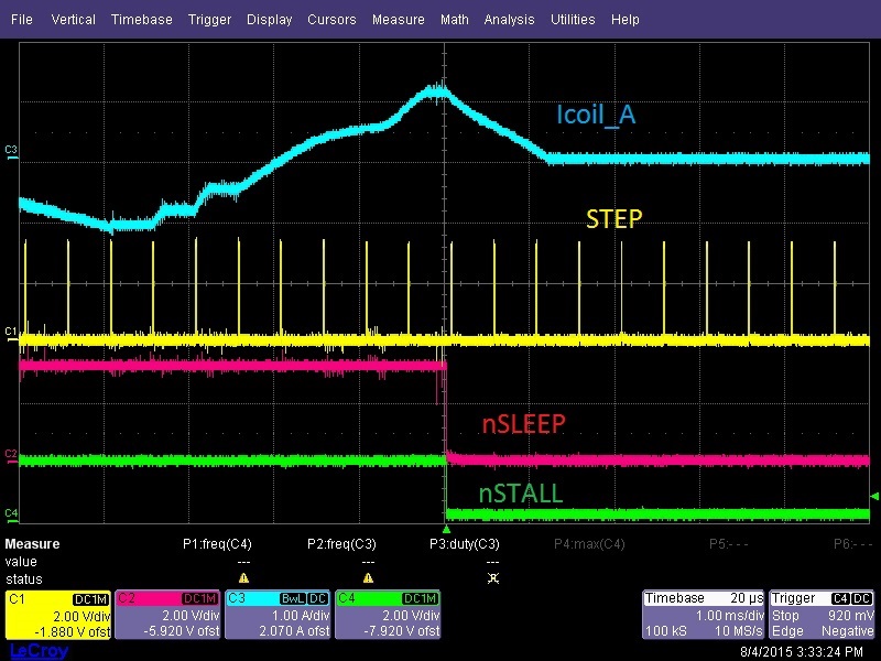
    In my setup I have only altered the Eval board to have an external H/W Latch that takes the nSTALL flag as input, and then latches the nSLEEP (basically using nSTALL as an interrupt to SLEEP the H-Bridge to prevent excess driving into the End-Stop)

    As demonstrable proof of this feature, see picture below. (Note STEP keeps pulsing because I sleep the DRV8711 HBRIDGE, but do not mess with the driving uCPU so it keeps pulsing STEP)


    Now that I demonstrated from an application perspective and is really seeming like a good feature, I wished to probe the actual signal to optimize while seeing something (as opposed to just blindly varying FW parameters). This will let me provide the technical knowledge/justification on our business side of things.

    I did as you recommended by using External Stall Detect mode, and probing both the VBEMF_Analog signal (pin 20) while triggering/probing off the nBEMF (pin 19, which I call nBEMF_CLK).

    Now I am running into difficulty with interpreting the signals I am seeing.

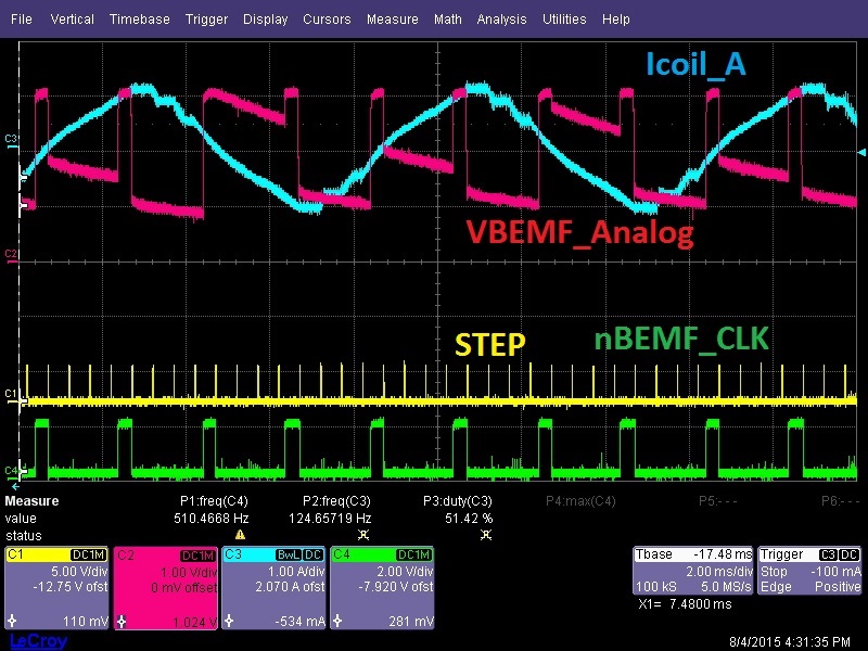
    This picture shows me driving the motor in 1 direction without any physical stall present, so these are merely the signals Icoil_A, VBEMF_Analog, STEP, and nBEMF_CLK. Note that I am running in 1/4-step Microstepping. You can see why I have a hard time viewing the VBEMF as there is a offset bias that seems to be all over the place depending on which part of the current-cycle the motor is at.

    What is the BEMF signal-of-interest in the picture below, given that we start sampling on the falling edge of nBEMF_CLK? Since we are programming an Integration time, is it the area under the VBEMF_Analog trace like an offset/bias? Or is it the Small-Signal riding on top of that slow drooping signal?

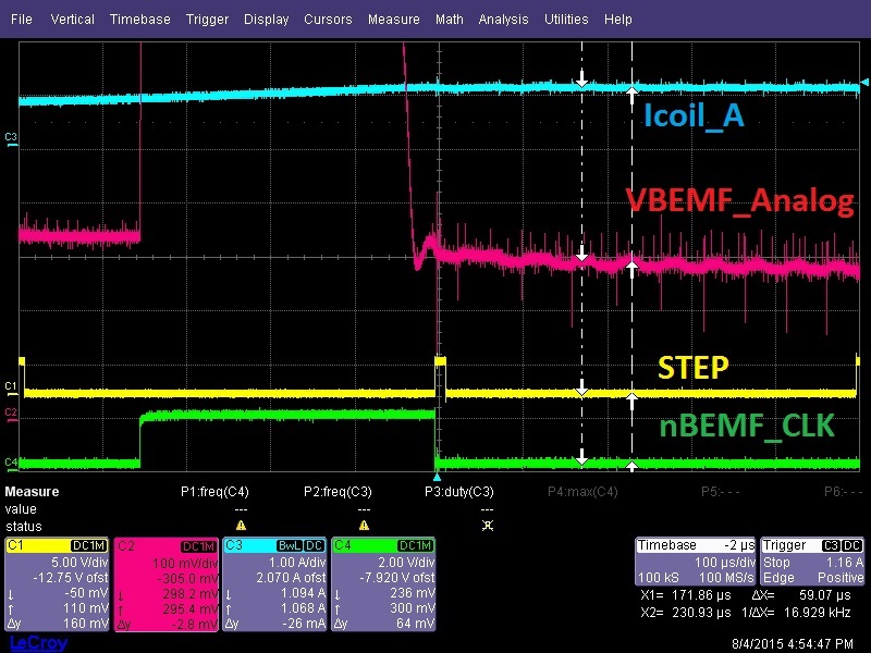
    Below is a zoomed in snapshot of the above picture on a luckily-measured sample where VBEMF_Analog was at a convenient location. Here you can see the small-signal ~16KHz wiggle I thought might be the VBEMF (if it wasn't the larger offset/bias signal).

    And since I haven't come up with a way to trigger off the Internal-Stall-Detect mode nSTALL while simultaneously probing the Analog signal, I have here a waveform showing the VBEMF_Analog while continuously driving into the Hard-Stop while stalled. I noticed in general the offset/bias is consistently lower (and mostly cyclic with the current waveform).

    This is a very cool feature and I wish you guys had an application note describing it in a bit more technical detail (as opposed to just saying it can be done empirically by varying parameters).

    I also have on my bench a TI-Competitor Motor Driver for evaluation simply because they have a part with a similar feature, but a much more descriptive application note. TI is my preferred vendor; hence the effort :).

    Thanks,

    -Ernie

  • I should add that if you look too carefully you will notice that (when BEMF_CLK is low) VBEMF_Analog in picture 3 is at a DC level of ~300mV, whereas the DC level of VBEMF_Analog in picture 2 is typically somewhere between [1,2] Volts. 

    This discrepancy is from the two pictures being taken in 2 different directions. (My mechanical load has different torque depending on which direction you go; this is a leadscrew moving a pressured enclosure, so compression requires more force than de-compression.)

  • Hi Ernie,

    The BEMF is measured at several 90, 180, 270, and 360 degrees in the indexer table. So, there are two measurements on the coil A and two measurement on coil B per electrical revolution.

    That is why there appears to be a measurement with the coil current at 100%.

    Another item to keep in mind is the resistance to ground of the scope probe. This can affect the reading by discharging the cap.

    Here are a few more suggestions to try when setting the SMPLTH, SDTHR, and VDIV. Zoom in on each coil as the current changes to 0 from the previous step. Measure how long it takes for the current to reach zero. Next subtract that value from the step period. That should be the maximum SMPLTH time.
    Reduce the SMPLTH setting to provide margin. I suggest you drop it 2 settings or ~50% if possible.
  • Great.

    What is the actual BEMF signal-of-interest in my waveforms (RED BEMF_ANALOG)? Is it the integration of the drooping DC-level signal while BEMF is low (GREEN) (pic2)? Or is it the integration of the smaller ~15KHz AC-sinusoidal-signal riding on this DC-signal (pic3)?
  • Hi Ernie,

    I have highlighted the BEMF and the coil the BEMF is associated with. The BEMF circuit is a sample hold circuit. It captures the BEMF based on the parameters in the register and will hold it until the next zero state on the opposite side. This assumes there is nothing to discharge the cap, such as a scope probe.

    The BEMF is a sinusoidal signal, which is why the value varies.

    See image below.

  • I understand now. Thank you Rick this has been excellent.

    I am convinced I can implement this feature in my new design. 

    Is the DRV8711 the only TI chip offering this feature? My application has several channels, with relatively low (0.75-1.5 A) requirement; hence an integrated H-Bridge would be cleaner.

    TI's integrated motor controller+integrated H-Bridges are nice, but I wasn't able to find one with the Integrated Stall Detection feature. 

  • Hi Ernie,

    I am glad to hear you can implement this feature.

    The DRV8711 is the only device offering the stall detect feature. None of the integrated H-bridge devices have it.

  • Feel free to move this to a new thread if it makes more sense.

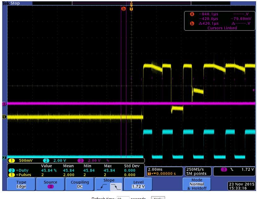
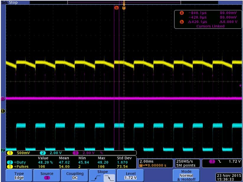
    More questions regarding the internal stall detection of the DRV8711. I’ve read through the info provided here and everything makes sense except the part where a stall is detected. I’m using a ½ step rate of 800uS and a SMPLTH time of 1ms. My motor drive voltage is approximately 12V so I used a voltage divide of 8 to get a full scale of about 1.5V which should correspond to a SDTHR of about 212 for a DAC with a 1.8V reference.   I’ve enabled the external stall option to get a trigger to view the divided BEMF on the output. The yellow trace is BEMF, the pink trace is the steps and the blue is the BEMFV signal. The 3 images below represent starting, running and stalled.

    I when the motor is running the BEMF is near the expected rail, when it is starting there are a few pulses below the rail until it gets moving. When it is stalled the voltage is near 0.

    I guess this is where my understanding of the stall detection feature breaks down. The first highlighted part of the datasheet below seems to indicate that I could pick almost any value for SDTHR and it should work because it is above the threshold when it is running and below it when it is stalled. But the second highlighted part says it has to see a drop. If you are at a stop and attempt to move but fail will a stall be generated?

    I’ve been tinkering with this for way too long. What am I missing?

    7.3.10.1 Internal Stall Detection
    To use internal stall detection, the EXSTALL bit in the CTRL register is set to 0. In this mode, the STALLn/BEMFVn output pin is used to signal a valid stall condition.

    Step time, or rate at which step input is applied to DRV8711, has to be greater than SMPLTH time for back EMF sampling.

    Using internal stall detection, a stall is detected when the sampled back EMF drops below the value set by the SDTHR bits in the STALL register. A programmable counter circuit allows the assertion of the STALLn output to be delayed until the back EMF has been sampled below the SDTHR value for more than one zero-current step The counter is programmed by the SDCNT bits in the STALL register, and provides selections of 1, 2, 4, or 8 steps.

    When the stall is detected (at the end of a SMPLTH interval), the STALLn/BEMFVn pin is driven active low, and the STD bit and the STDLAT bit in the STATUS register are set. The STALLn/BEMFVn pin will deassert and the STD bit will automatically clear at the next zero-current step if a stall condition is not detected, while the STDLAT bit will remain set until a 0 is written to it. The STDLAT is reset when the STD bit clears after the first zero-cross step that does not detect a stall condition.

    This stall detection scheme is only effective when the motor is stalled while running at or above some minimum speed. Because it relies on detecting a drop in motor back EMF, the motor must be rotating with sufficient speed to generate a detectable back EMF. During motor start-up, and at very slow step rates, the stall detection is not
    reliable.

    Figure 1: Starting

     Figure 2: Running

     Figure 3: Stalled

  • I think I may have answered my own question.  I was reading this "Step time, or rate at which step input is applied to DRV8711, has to be greater than SMPLTH time for back EMF sampling."  to be the step rate had to be faster than the SMPLTH.  When it actually has to be slower.  The appositive in that sentence is very confusing.  It kind of reads the rate at which step input is applied to DRV8711, has to be greater than SMPLTH.

  • Hi Brian,

    Agreed, the appositive is confusing. It is less confusing written as "Step time has to be greater than SMPLTH time for back EMF sampling."

    We will add your comment into future datasheet updates.

    If you set the sampling time to less than the step time, do you achieve the desired results?
  • Hi Rick,


    You made a comment in one of your posts about timing that cleared it up for me.  A note in the datasheet or a wording change would probably help.

    In my minimal testing last night everything seemed to work just as expected.  There were a wide range of sample thresholds that worked for me.


    Thanks,


    Brian